Electronic instrument for refrigerant recovery machine

a technology of electronic instruments and refrigerant recovery machines, which is applied in refrigeration machines, lighting and heating equipment, domestic cooling equipment, etc., can solve the problems of complicated installation of piping, inconvenient refrigerant drawing, and inconvenient refrigerant drawing,

Inactive Publication Date: 2011-06-09
SUN WONDER INDAL
View PDF3 Cites 17 Cited by
  • Summary
  • Abstract
  • Description
  • Claims
  • Application Information

AI Technical Summary

Benefits of technology

[0006]The present invention has been accomplished under the circumstances in view. It is the main object of the present invention to provide an electronic instrument for refrigerant recovery machine, which detects the pressure of the pipes in the refrigerant recovery machine and compares the detected pressure values with predetermined pressure threshold limit values, and then controls the operation of the refrigerant recovery machine subject to the pressure comparison results, enabling the refrigerant recovery machine to draw the refrigerant from the main unit of a refrigerator or cooler accurately and safely.
[0007]It is another object of the present invention to provide an electronic instrument for refrigerant recovery machine, which detects the temperature of the pipes in the refrigerant recovery machine and compares the detected temperature values with a predetermined temperature threshold limit value, and then controls the operation of the refrigerant recovery machine subject to the temperature comparison result, enabling the refrigerant recovery machine to draw the refrigerant from the main unit of a refrigerator or cooler accurately and safely.

Problems solved by technology

However, these mechanical safety switches have a broad range of pressure error and tend to cause an incomplete refrigerant drawing problem.
Further, these mechanical safety switches are commonly heavy and expensive, increasing the cost of the refrigerant recovery machine and complicating the installation of the piping.
Further, during the operation of a refrigerant recovery machine, the pipes of the refrigerant recovery machine may be clogged with the dirty refrigerant.
Clogging of the pipes may cause freezing of the refrigerant, resulting in an abnormal pressure value and affecting the drawing of the refrigerant.

Method used


Image

  • Electronic instrument for refrigerant recovery machine
  • Electronic instrument for refrigerant recovery machine
  • Electronic instrument for refrigerant recovery machine

Examples


Embodiment Construction

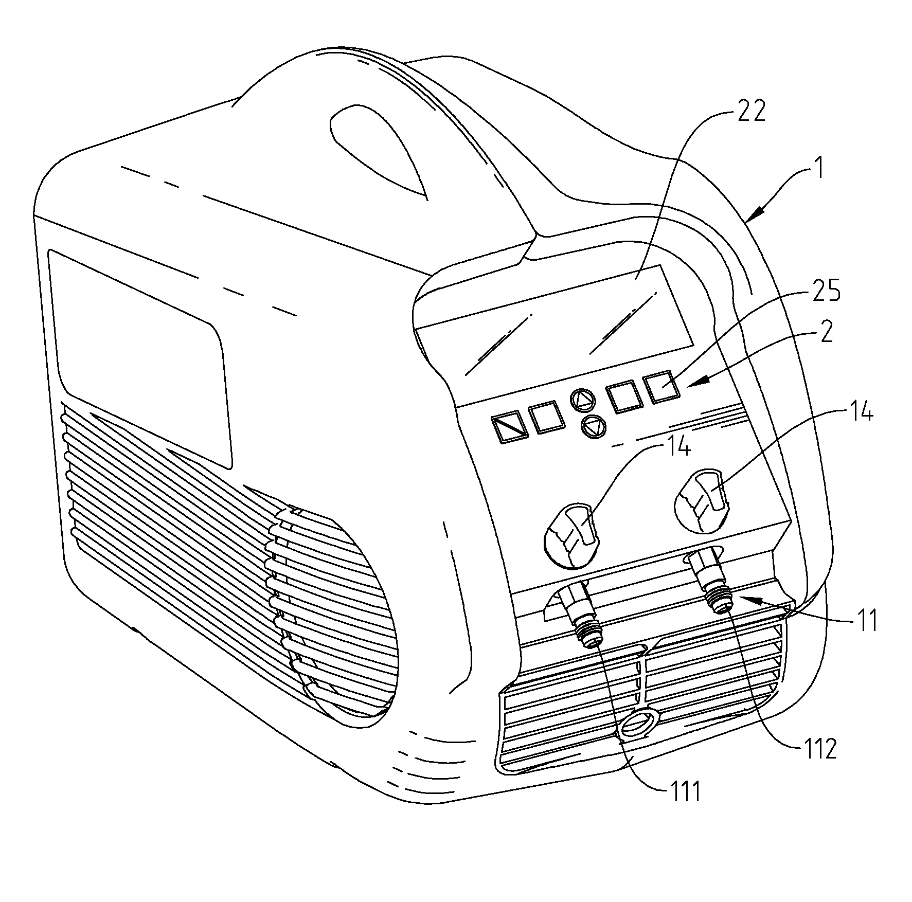
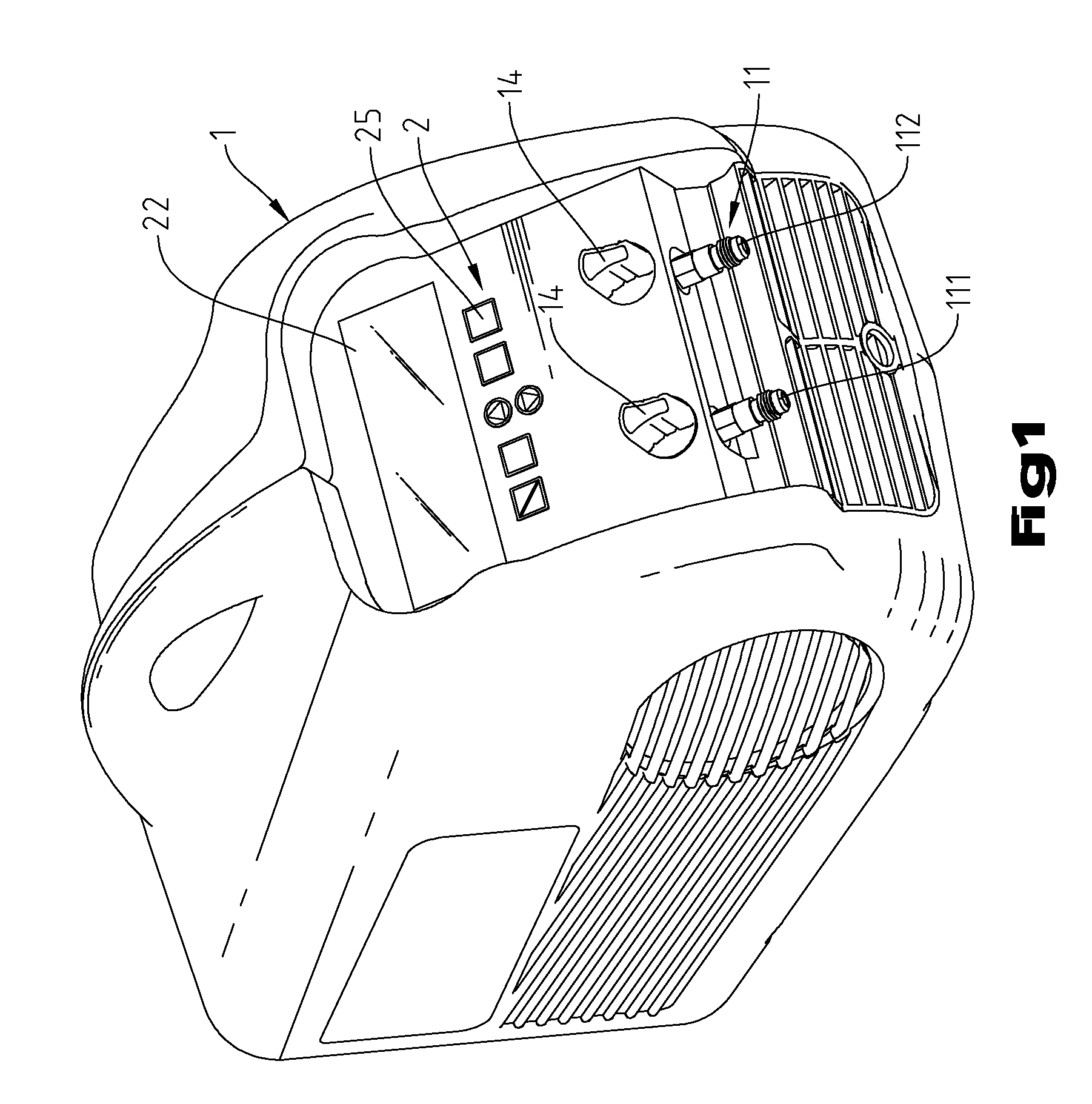
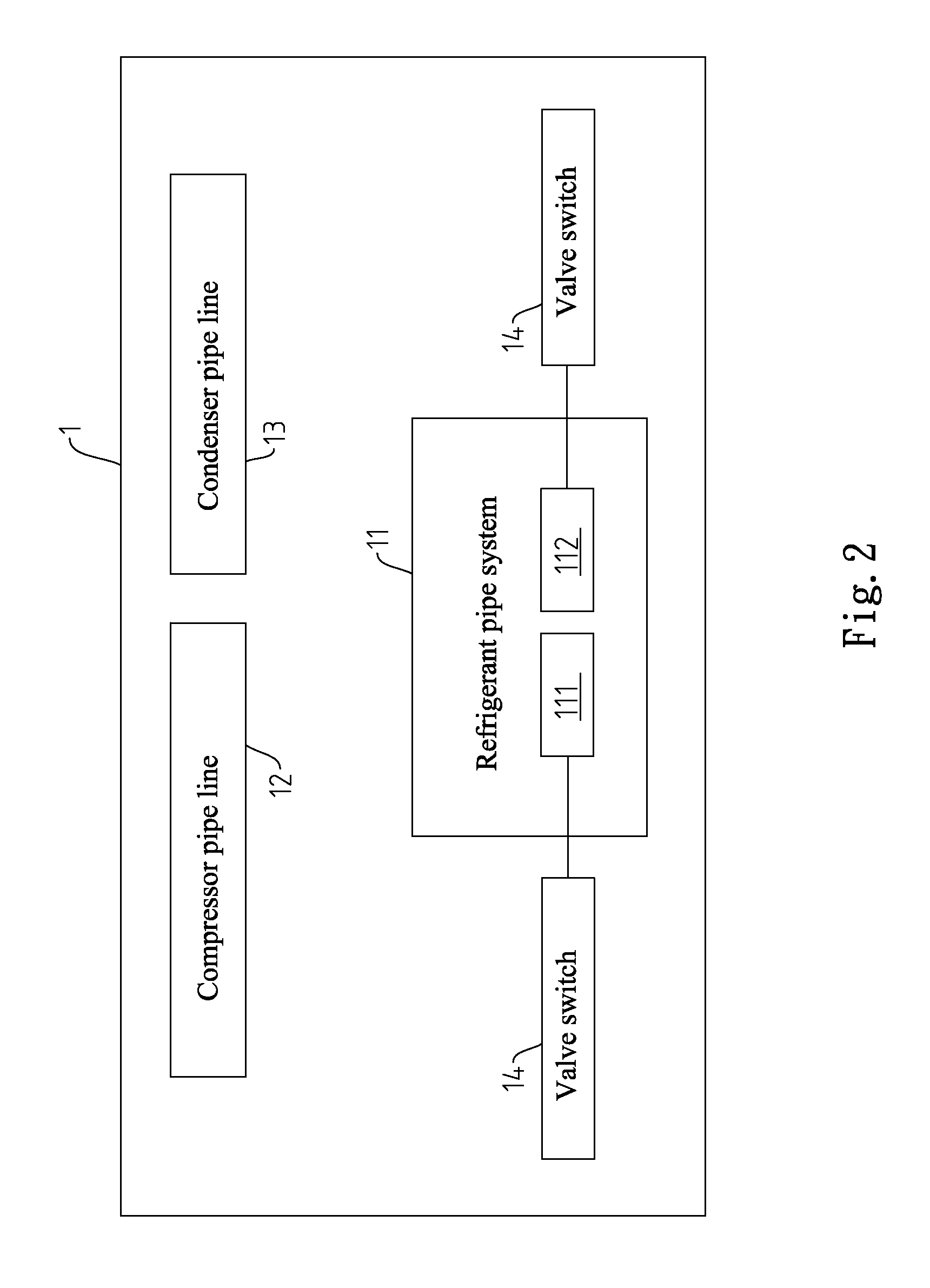
[0012]Referring to FIGS. 1-3, a refrigerant recovery machine 1 is shown carrying an electronic instrument 2. The refrigerant recovery machine 1 has mounted therein a refrigerant pipe system 11, a compressor pipe line 12 and a condenser pipe line 13. The refrigerant pipe system 11 comprises an input pipe 111 and an output pipe 112. Valve switches 14 are respectively in the input pipe 111 and the output pipe 112 for controlling closing / opening of the respective passages. The electronic instrument 2 comprises a control unit 21, a LCD (Liquid Crystal Display) device 22, a pressure sensor unit 23, a temperature sensor unit 24, operating buttons 25 and an alarm 26. The LCD (Liquid Crystal Display) device 22, the pressure sensor unit 23, the temperature sensor unit 24, the operating buttons 25 and the alarm 26 are respectively electrically connected to the control unit 21.

[0013]The control unit 21 comprises a microprocessor 211, a multiplexer 212 and an operation amplifier 213. The micropr...


PUM


Abstract

Used in a refrigerant recovery machine having a refrigerant input pipe and a refrigerant output pipe, an electronic instrument is disclosed to include a control unit, a LCD device controllable by the control unit to display the operation status of the refrigerant recovery machine, and a pressure sensor unit having an input pipe pressure sensor and an output pipe pressure sensor for detecting the pressure in the input pipe and the pressure in the output pipe and transmitting the respective detected pressure values to the control unit for comparison with a pre-set pressure threshold limit value so that the control unit controls the operation of the refrigerant recovery machine subject to the comparison results.

Description

BACKGROUND OF THE INVENTION[0001]1. Field of the Invention[0002]The present invention relates to refrigerant recovery technology and more particularly, to an electronic instrument for use in a refrigerant recovery machine to control the operation of the refrigerant recovery machine in collecting the refrigerant from the main unit of a cooler or refrigerator.[0003]2. Description of the Related Art[0004]A refrigerant recovery machine is adapted to draw the refrigerant out of the main unit of a system (room cooler, car cooler, central air conditioning system or refrigerator) into a recovery tank. However, a conventional refrigerant recovery machine must be equipped with an extra high-pressure mechanical type safety pressure switch and an extra mechanical vacuum type safety pressure switch. These two safety switches are respectively connected to the valve blocks in the refrigerant input pipe and refrigerant output pipe of the refrigerant recovery machine. When the input or output pressu...

Claims


Application Information

Patent Timeline
Patent Type & Authority Applications(United States)
IPC IPC(8): F25D25/00
CPCF25B45/00F25B2345/002F25B2700/21F25B2345/0051F25B2700/19F25B2345/003
Inventor CHANG, AN-CHAO
Owner SUN WONDER INDAL
Why Eureka
Try Eureka