
Cable with electrical conductor included therein

a technology of electrical conductors and cables, applied in the direction of insulated conductors, cables, cable terminations, etc., can solve the problems of affecting the conductor, affecting the conductor, and reducing the service life of the cable,

Active Publication Date: 2011-06-09
HELUKABEL
View PDF32 Cites 4 Cited by
  • Summary
  • Abstract
  • Description
  • Claims
  • Application Information

AI Technical Summary

Benefits of technology

[0008]Experiments have shown that because of the particular stress situation during the thermal stretching, an intimate positive-fit connection between the two elements occurs, which is accompanied by a permanent deformation of the cable and possibly also of the conductor, i.e. the cable accommodates to the external contour of the conductor, which is at the same time compressed by the compressive forces which occur, acting inwardly, so that when the cable is subsequently subjected to tensile stress in operation, the risk of impairment to the conductor as a result of the compressive forces acting from the outside and also the risk of the conductor's breaking can be reduced substantially or even eliminated virtually completely.
[0009]An appropriate embodiment is characterised by the fact that the conductor is braided or coiled around a core. Thanks to this measure, the conductor obtains an elongation reserve, so that there is virtually no risk of breaking any longer.
[0010]It may be provided that a cable is contained in the braided cable which has an insulated cylindrical core, an insulating, compressible compensating layer enclosing the core, a braided or coiled conductor on the compensating layer, and an insulating casing layer enclosing the conductor. The arrangement of a compressible compensating layer reduces the effects of the compressive forces of the cable still further. The compensating layer may be resiliently or elastically compressible, such as in the form of a layer of foam.
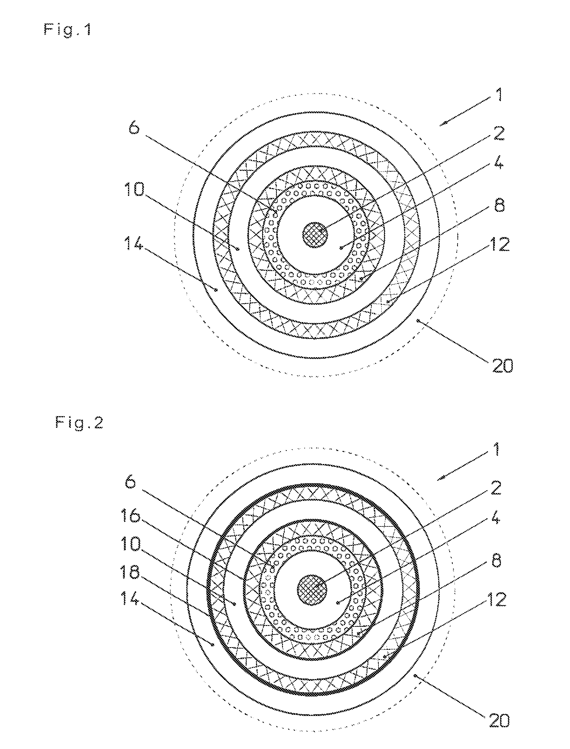
[0011]It may also be provided that a further braided or coiled conductor is arranged on the casing layer, which is enclosed by a further insulating casing layer. The electrical twin-wire structure formed in this way offers advantages when transmitting data and supplying electricity.
[0012]A protective film of plastic my be disposed between the conductor and the casing layer, especially consisting of PTFE, optionally with a corresponding further protective film between the further conductor and the further casing layer. These films serve to provide security in case the insulation capacity of the casings is impaired by the stretching process.
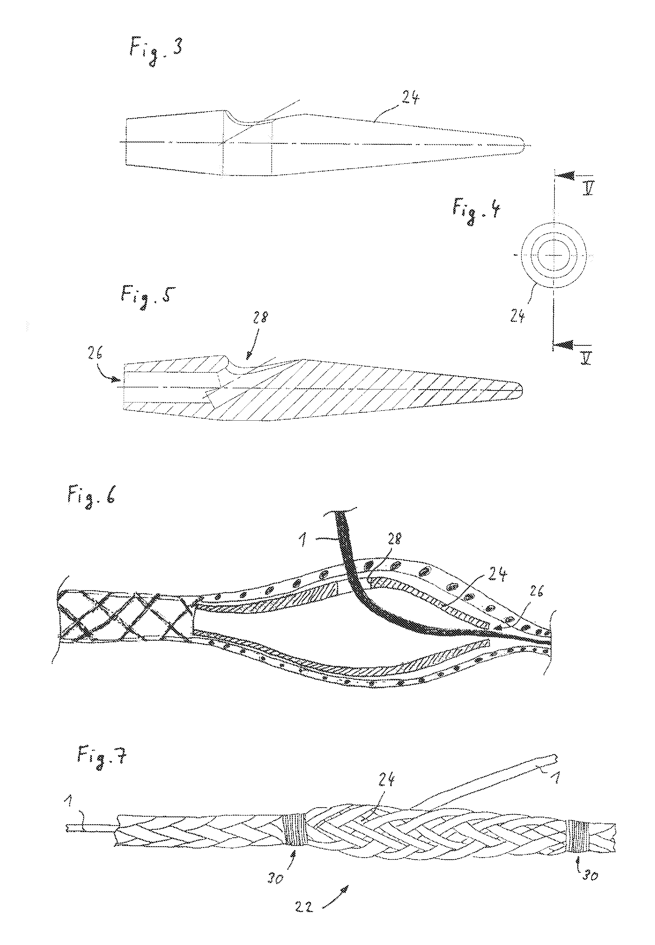
[0030]In a preferred further development of the invention, it can be provided that a splaying member with rounded external contours is disposed inside the cable at a cable exit point of the cable, having a central passage opening from which an exit opening leaves, leading to the outside, the at least one electric conductor being guided through the passage opening into the splaying member, through the exit opening and out of it, and through which splayed cables are guided to the outside. This measure ensures that the conductor can be guided out of the cable at any point desired, without any risk of pinching or detaching the conductor if the cable is exposed to a tensile load.

Problems solved by technology

Experiments have shown that because of the particular stress situation during the thermal stretching, an intimate positive-fit connection between the two elements occurs, which is accompanied by a permanent deformation of the cable and possibly also of the conductor, i.e. the cable accommodates to the external contour of the conductor, which is at the same time compressed by the compressive forces which occur, acting inwardly, so that when the cable is subsequently subjected to tensile stress in operation, the risk of impairment to the conductor as a result of the compressive forces acting from the outside and also the risk of the conductor's breaking can be reduced substantially or even eliminated virtually completely.

Method used


Image

  • Cable with electrical conductor included therein
  • Cable with electrical conductor included therein
  • Cable with electrical conductor included therein

Examples


Embodiment Construction

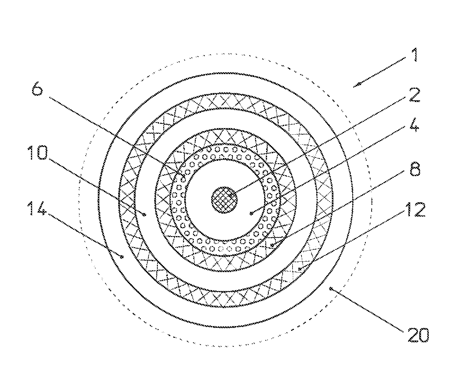
[0040]FIG. 1 shows the structure of a cable 1 in a cross-sectional illustration for coaxially arranging inside a braided plastic cable 20, which is merely indicated and which is to be thermally stretched together with the cable contained therein.

[0041]An insulating cylindrical core of the cable 1 includes a support element 2, consisting of a PA monofilament with a diameter of about 0.5 mm, on which is extruded a hard core layer 4 of PP with an external diameter of about 1.6 mm.

[0042]An insulating, resiliently compressible compensating layer 6 is extruded around the core formed in this way, which, in the example illustrated, may have an external diameter of about 2.2 mm+ / −0.1 mm and may consist of foamed LD-PE. Alternatively, the compensating layer may consist of a thermoplastic elastomer, such as PE, PP, PVC or the like, which is combined with non-thermoplastic components, such as butadiene components. It is also possible to use cross-linked materials (with beta radiation, for examp...


PUM

PropertyMeasurementUnit
Temperatureaaaaaaaaaa

Abstract

The invention is directed to a braided chemical fibre cable in which at least one electric conductor is contained, in which the cable is thermally stretched together with the conductor contained therein.

Description

CROSS-REFERENCE TO RELATED APPLICATIONS[0001]This application is a national phase filing of PCT / DE2008 / 001713 filed on Oct. 20, 2008, claiming priority to DE 102007050402.2 filed on Oct. 19, 2007 in Germany.TECHNICAL FIELD[0002]The invention relates to a braided plastic or chemical fibre cable, in which at least one electric conductor is contained, and a method of producing such a cable.BACKGROUND OF THE INVENTION[0003]A traction cable with at least one integrated electric cable, such as for transmitting data or supplying electricity, frequently has to satisfy extreme requirements regarding the mechanical, chemical and electric properties, such as minimal weight, maximum breaking strength, minimal susceptibility to torsion, minimal stretching, floatability, fatigue strength under reversed bending stresses, at least two-core electric connection for transmitting data or supplying electricity, and others.[0004]Major problems consist in the fact that a braided cable exerts considerable ...

Claims


Application Information

Patent Timeline
IPC IPC(8): H02G15/02H01B7/00
CPCD04C1/12D07B1/025D07B2501/406D07B2401/201D07B2207/4045D07B2205/205D07B2205/2042D07B2205/2014D07B2201/2095D07B1/147D07B5/12D07B7/16D07B2201/1096D07B2801/10D07B2801/60
Inventor STRUWE, HANSJORGKIRST, RUDOLF F.
Owner HELUKABEL
Learn More