

Mis-fuel inhibitor
- Summary
- Abstract
- Description
- Claims
- Application Information
AI Technical Summary
Benefits of technology
Problems solved by technology
Method used
Image

Examples
Embodiment Construction
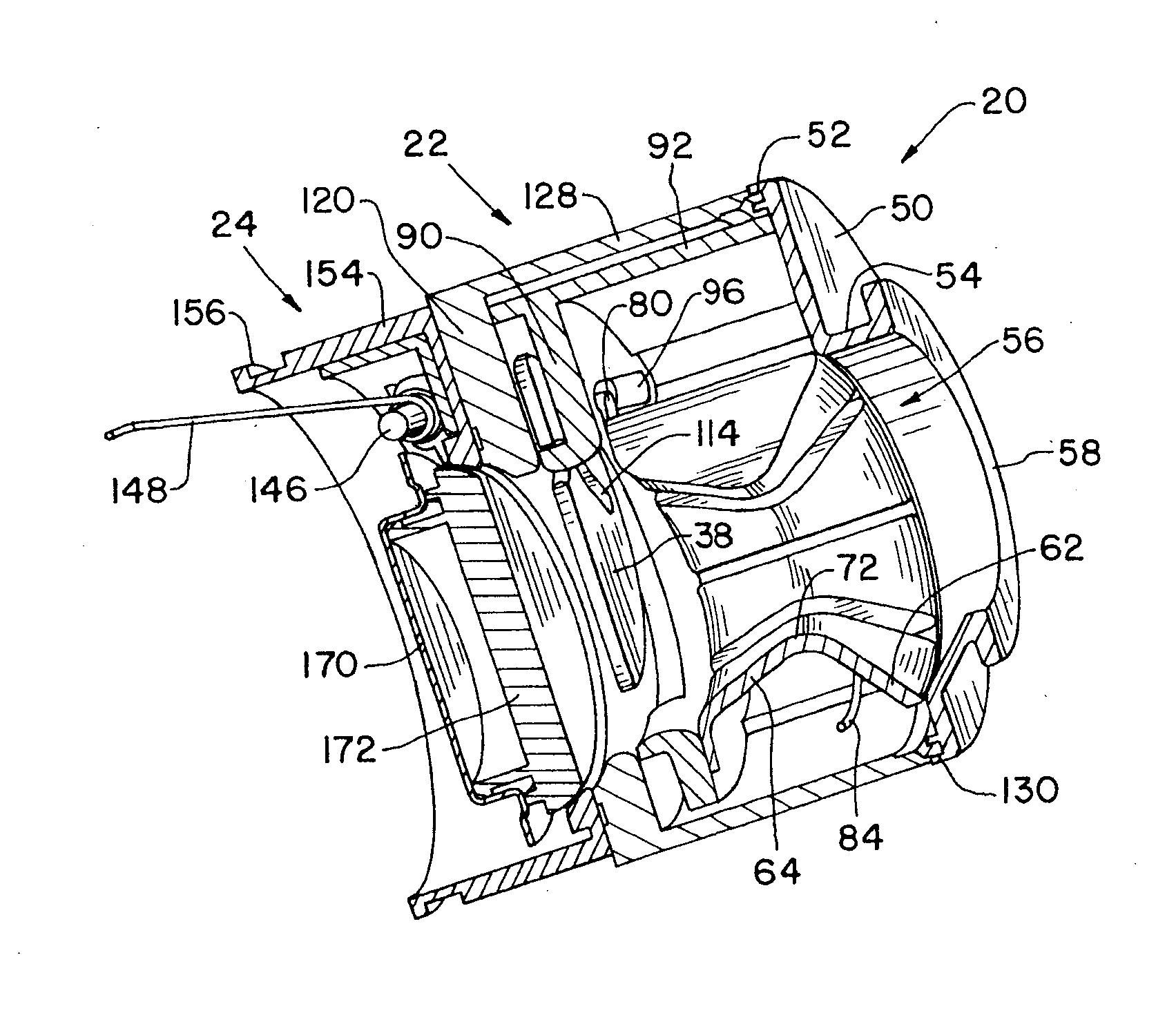
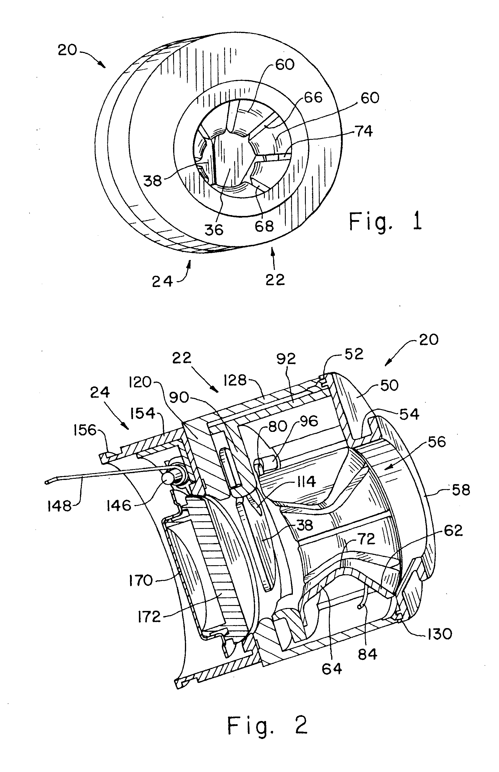
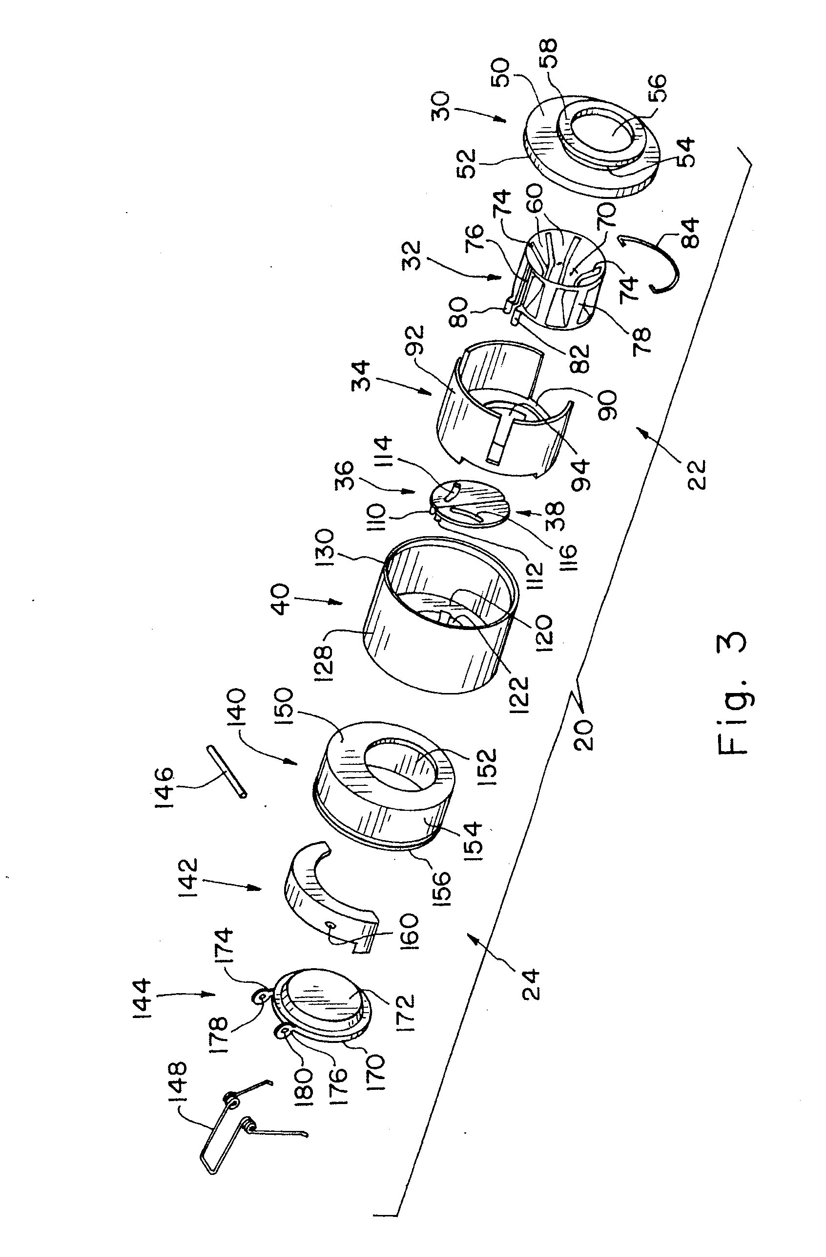
[0031]Referring now more specifically to the drawings and to FIGS. 1 and 2 in particular, a vehicle fuel system inlet neck assembly 20 is shown having a mis-fuel inhibitor 22 as a part thereof for preventing the insertion of a refueling nozzle that is smaller in diameter than the nozzles provided for the intended fuel. Refueling system 20 is shown as a capless refueling system having a primary shutoff valve 24; however, those skilled in the art will readily recognize that mis-fuel inhibitor 22 can be incorporated into the inlet neck of a vehicle fuel system having an outer cap thereon as well. The capless structure shown is merely one suitable arrangement in which the mis-fuel inhibitor can be used advantageously, but is not intended to limit applications and uses of the present invention, nor the scope of the claims that follow.
[0032]Mis-fuel inhibitor 22 includes an outer cover 30, an actuator 32, an actuator inner housing 34, first and second shutters 36, 38 and an actuator outer...
PUM
| Property | Measurement | Unit |
|---|---|---|
| Diameter | aaaaa | aaaaa |
| Separation | aaaaa | aaaaa |
Abstract
Description
Claims
Application Information