

Low bypass fine arrestor
a technology of arrestor and fine, which is applied in the direction of overvoltage protection resistor, emergency protective arrangement for limiting excess voltage/current, coupling device connection, etc., which can solve the problem that the surge level of line or equipment damage may still pass through the surge device, increasing manufacturing time and cost requirements
- Summary
- Abstract
- Description
- Claims
- Application Information
AI Technical Summary
Benefits of technology
Problems solved by technology
Method used
Image

Examples
Embodiment Construction
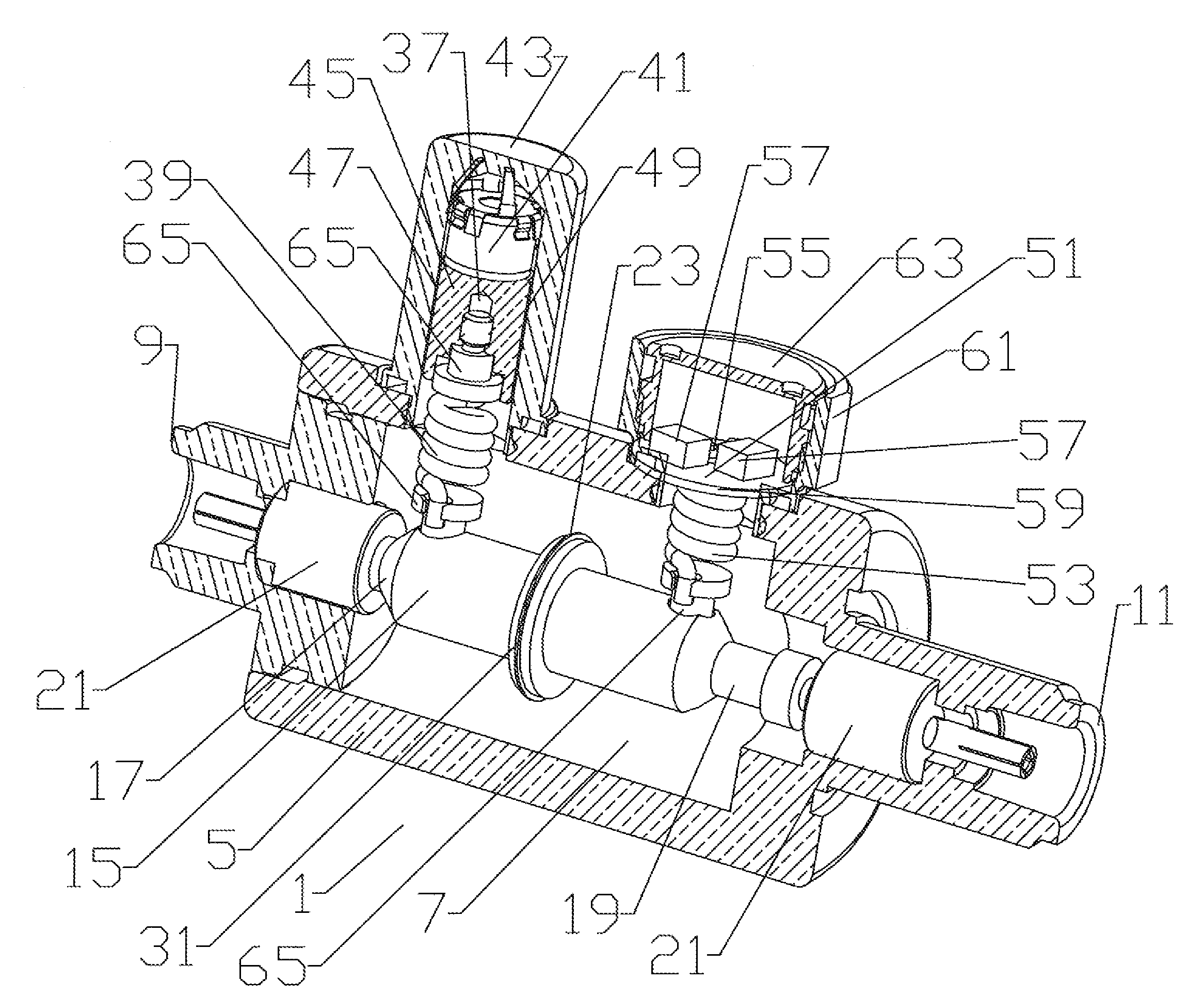
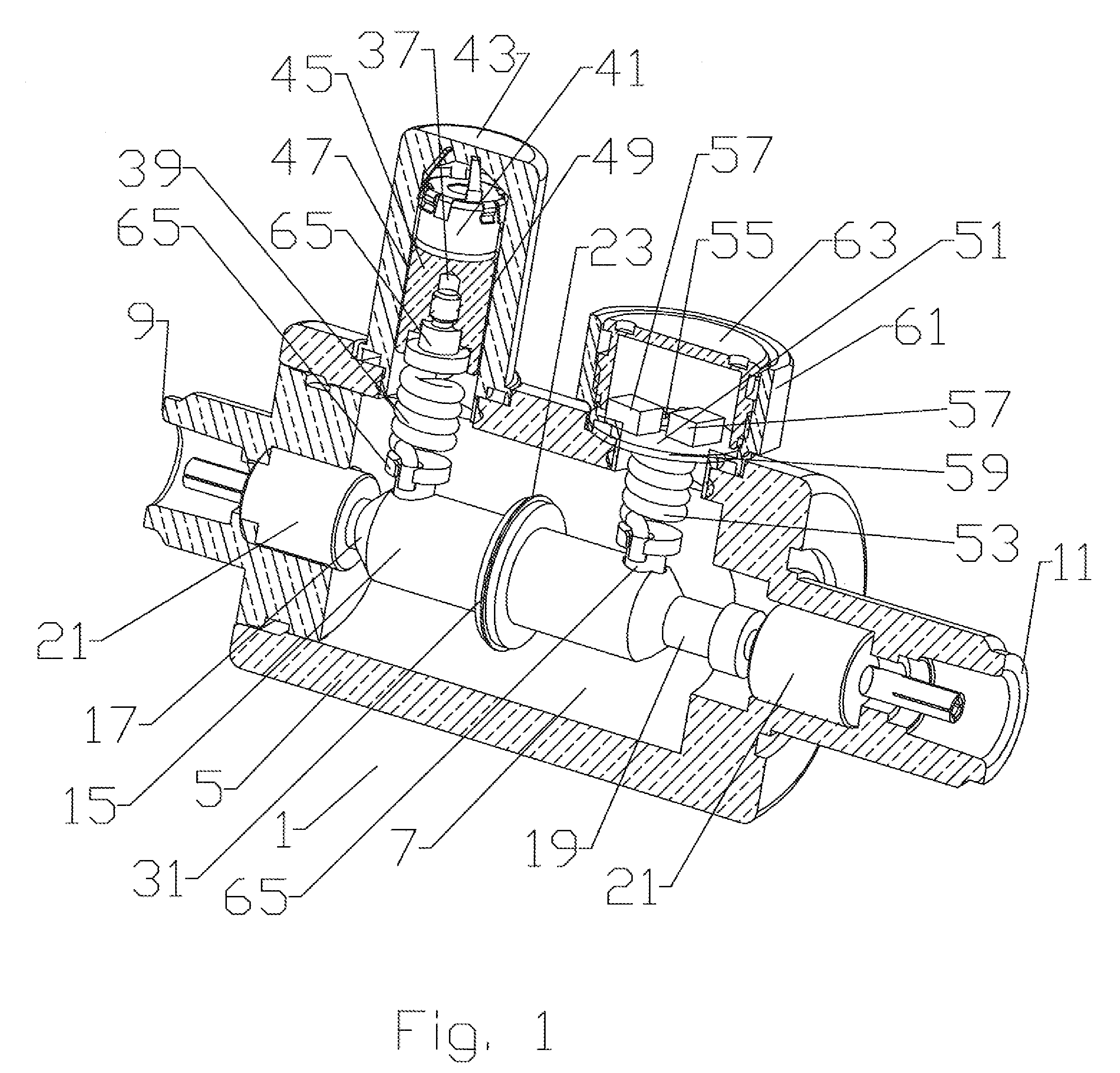
[0018]The inventors have analyzed presently available Fine Arrestor units and discovered they frequently fail to provide a promised minimum level of surge pass through. Because of the common chamber and extended leads of and between the various electrical components the inventors have hypothesized that cross coupling between the circuit elements is occurring as a result of the high levels of electromagnetic fields / energy present when a surge occurs. The present invention minimizes opportunities for cross coupling by isolating the various circuit elements from each other and eliminating and or minimizing the length of any interconnecting leads. The result is a surprising and dramatic reduction in the level of surge bypass in a fine arrestor according to the invention.
[0019]A first embodiment of a fine arrestor 1 according to the invention is demonstrated in FIGS. 1 and 5. A body 5 has a bore 7 extending between first and second connection interfaces 9, 11. The first and second connec...
PUM
| Property | Measurement | Unit |
|---|---|---|
| dielectric constant | aaaaa | aaaaa |
| dielectric constant | aaaaa | aaaaa |
| dielectric constant | aaaaa | aaaaa |
Abstract
Description
Claims
Application Information