Feed through and common ground for electrical cables

a technology of electrical cables and feed through, applied in the direction of coupling device details, coupling device connection, connection contact member materials, etc., can solve the problems of significant manufacturing costs, significant manufacturing costs, and increased cost of grounding bus,

Inactive Publication Date: 2005-05-10
ANDREW LLC
View PDF23 Cites 29 Cited by
  • Summary
  • Abstract
  • Description
  • Claims
  • Application Information

AI Technical Summary

Benefits of technology

[0026]The first embodiment is demonstrated as a 12 electrical cable configuration. In alternative embodiments, the number of electrical cables the FCGEC 1 is adapted to receive may be varied. For common interconnection of electrical cable outer conductors where a feedthrough is not required, for example along an exterior cable run or near the top of an antenna tower, a second embodiment as shown in FIGS. 6-8 may be applied. Here, like components similarly notated, the ground strap 9 may be isolated except for the protruding connection point 20 by enclosure between an oversized support insulator 7 and retaining insulator 11. Also, support insulator 7 to retaining insulator 11 direct contact is applied on both sides of the ground strap 9, along the longitudinal axis of the electrical cable. To further improve the sealing effect of the respective insulators upon and around each outer conductor of the electrical cables, sealing fin(s) 29 may be applied to cable outer conductor contacting surfaces of each insulator adapted to mate with corrugations in the outer conductor of the cable.
[0027]The present invention provides a cost effective common coupling solution with a reduced number of components. Installation is simplified by the wide common aperture 21 available for inserting each cable and the ability of the ground strap to retain each cable prior to final installation of the fastening plate 13. Because the ground strap is formed from a single piece of material, costs may be reduced and the opportunity for faulty installation minimized. In embodiments without bulkhead penetration features, the invention similarly reduces costs and installation requirements.

Problems solved by technology

Individual interconnections with each cable and then to a grounding bus create a significant cost which increases with each additional cable that requires grounding.
Further, each individual interconnection must be tightened to a specified torque level or the electrical resistance across the interconnection may unacceptably vary.
The large number of discrete components and interconnections involved resulting in prior solutions with significant manufacturing costs, installation labor requirements and administrative overhead.

Method used


Image

  • Feed through and common ground for electrical cables
  • Feed through and common ground for electrical cables
  • Feed through and common ground for electrical cables

Examples


Embodiment Construction

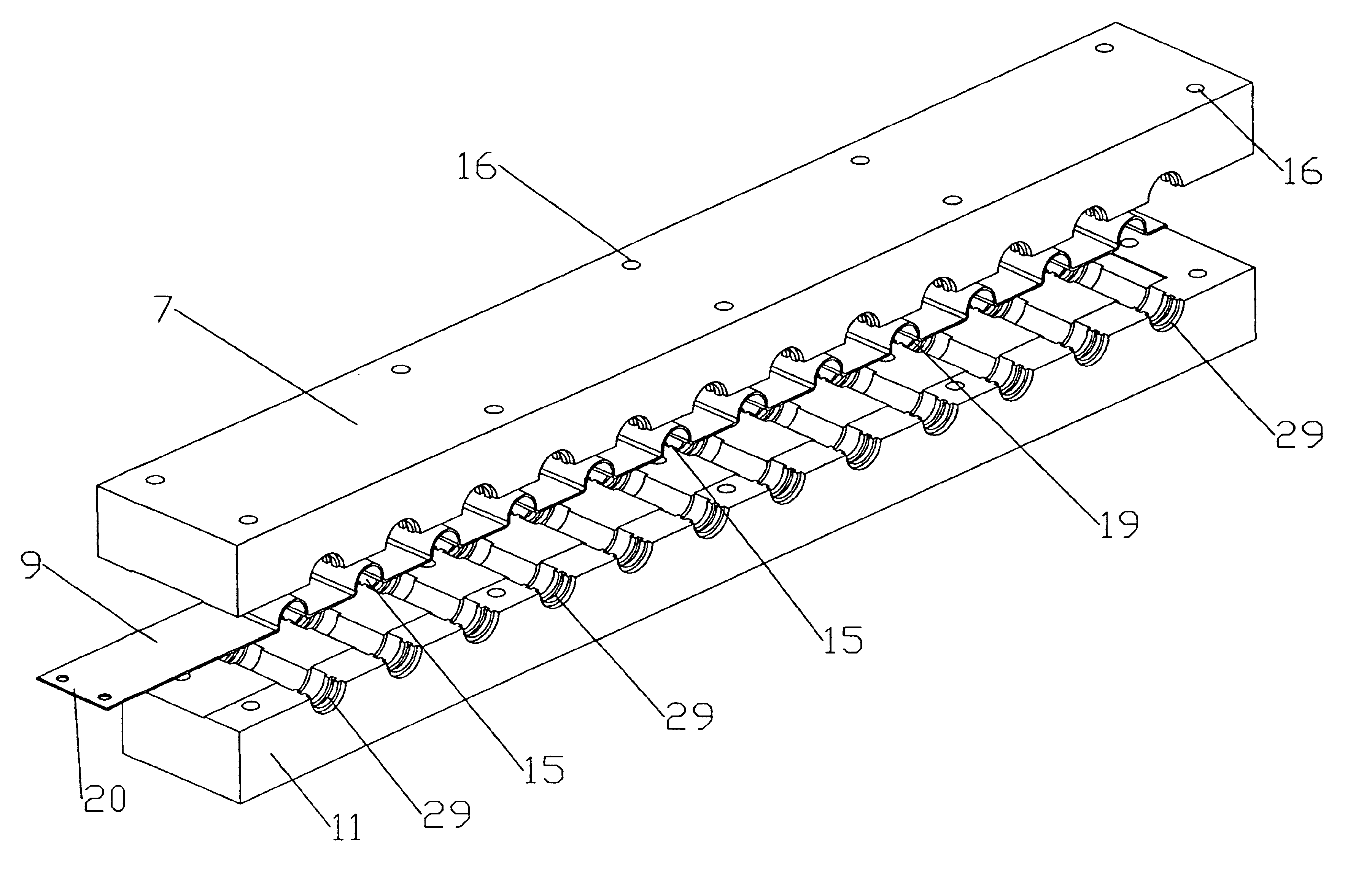
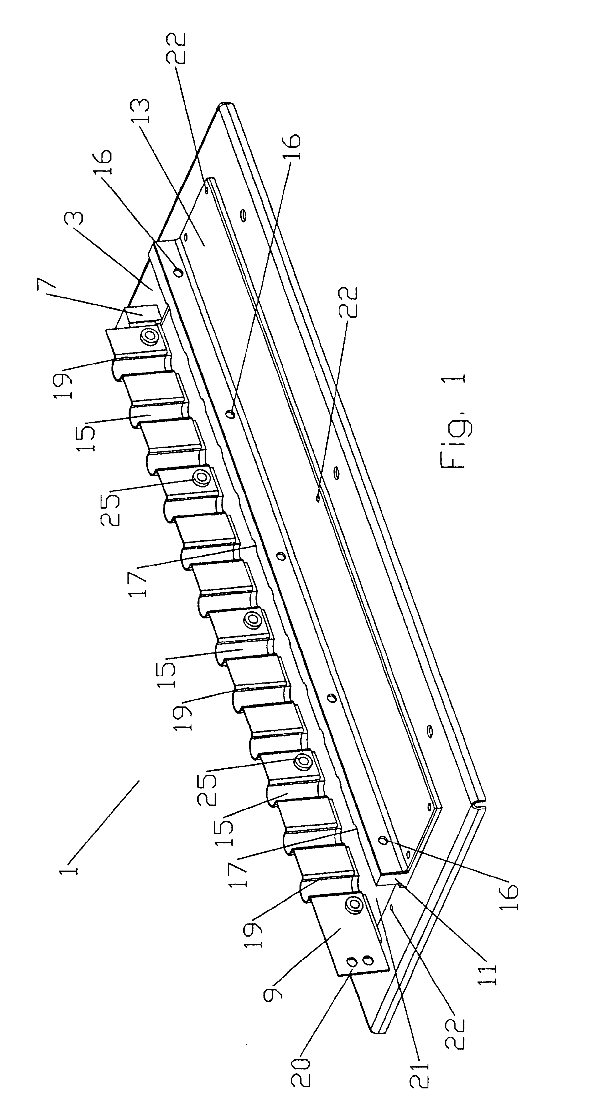
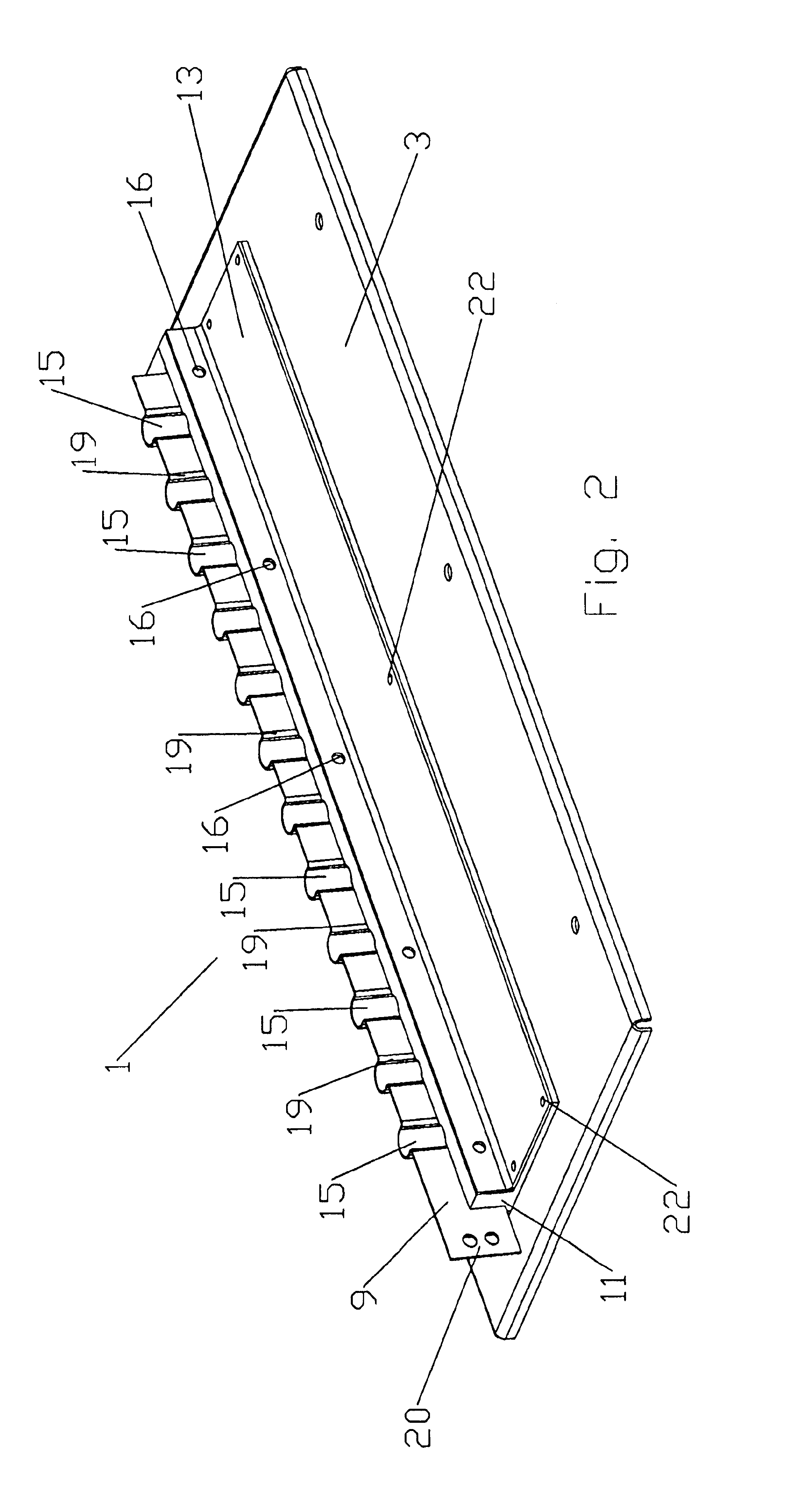
[0019]The invention is described in an exemplary first embodiment with reference to the various views of the first embodiment shown in FIGS. 1-5. The invention is described herein with respect to an electrical cable having an outer conductor. The electrical cable may be any type of, for example, coaxial cable, waveguide, multiple conductor cable or the like. Further, different types of electrical cable may be coupled together by the invention.

[0020]A feedthrough and common ground for electrical cables (FCGEC) 1 according to the first embodiment of the invention has a base plate 3 with an inward projecting flange 5 against which a support insulator 7 is seated. The support insulator 7 supports, electrically isolated from the base plate 3, a ground strap 9. A retaining insulator 11 and a fastening plate 13 are adapted to mate with the ground strap 9 to secure electrical cables (not shown) installed within a plurality of cable receiving portion(s) 15 formed in the ground strap 9. A plu...


PUM


Abstract

A common ground assembly for a plurality of electrical cables with a ground strap having a plurality of cable retaining portions adapted to receive and contact the outer conductor of each electrical cable. Inwardly projecting lip edges may be formed in the cable retaining portions to retain each electrical cable within a cable retaining portion. The ground strap may be electrically isolated from surrounding structure by a support insulator and a retaining insulator with cable retaining portions adapted to further urge each outer conductor into electrical contact with a cable retaining portion. If integrated with a feedthrough in the form of a base plate with an aperture, a flange of the baseplate may support the support insulator and a fastening plate may be used to compress the retaining insulator towards the ground strap, the fastening plate dimensioned to cover the aperture.

Description

BACKGROUND OF INVENTION[0001]1. Field of the Invention[0002]The invention relates to apparatus for electrical cable coupling. More particularly, the invention relates to a cost effective coupler for multiple electrical cables that may incorporate bulkhead penetration, useful as a component of a lightning protection system.[0003]2. Description of Related Art[0004]Electrical cables, for example coaxial transmission lines of antenna towers, are grounded to provide an electrical path to ground for dissipation of electrical current resulting from, for example, static discharge and or lightning strikes. Industry standards such as IEC 1024-1 and MIL-STD-188-124A have been developed to ensure that the grounding electrical circuit can handle expected current and voltage levels. According to these standards, each part of the grounding electrical circuit is provided with, for example, galvanically compatible interconnections having a minimal cross connection resistance of less than 1 milliohm ...

Claims


Application Information

Patent Timeline
Patent Type & Authority Patents(United States)
IPC IPC(8): H01R9/05H01R4/64H01R13/648
CPCH01R9/0524H01R4/646H01R13/648
Inventor THORBURN, NEIL
Owner ANDREW LLC
Why Eureka
Try Eureka