

Imaging device
a technology of imaging device and lens, which is applied in the direction of instruments, television systems, color signal processing circuits, etc., can solve the problems of consuming a large amount of power, increasing the size and cost of imaging devices, and complicated configuration of imaging devices
- Summary
- Abstract
- Description
- Claims
- Application Information
AI Technical Summary
Problems solved by technology
Method used
Image

Examples
first embodiment
[0046]In a first embodiment, one of single-eye images having the highest luminance difference between pixels is selected as the in-focus image. When an image is in focus, the contrast of the image becomes high and the luminance difference between a pixel having the highest luminance level and a pixel having the lowest luminance level in the image becomes large. Based on this fact, the highest luminance level and the lowest luminance level of pixels in each single-eye image are detected and a single-eye image where the difference between the highest and lowest luminance levels is the highest among the single-eye images is extracted as the in-focus image. In the example of FIG. 7, the single-eye image I5 is extracted as the in-focus image.
[0047]FIG. 8 is a flowchart showing a process of extracting an in-focus image according to the first embodiment. The image capturing unit 11 captures (or receives) the compound-eye image 8 shown in FIG. 7 obtained by the image sensor 4 and separates ...
second embodiment
[0049]In a second embodiment, a pixel having the extreme luminance level (the highest luminance level or the lowest luminance level) is extracted from each set of corresponding pixels, which correspond to the same field of view, of single-eye images, and an in-focus image is synthesized from the extracted pixels (pixels extracted from all sets of corresponding pixels).
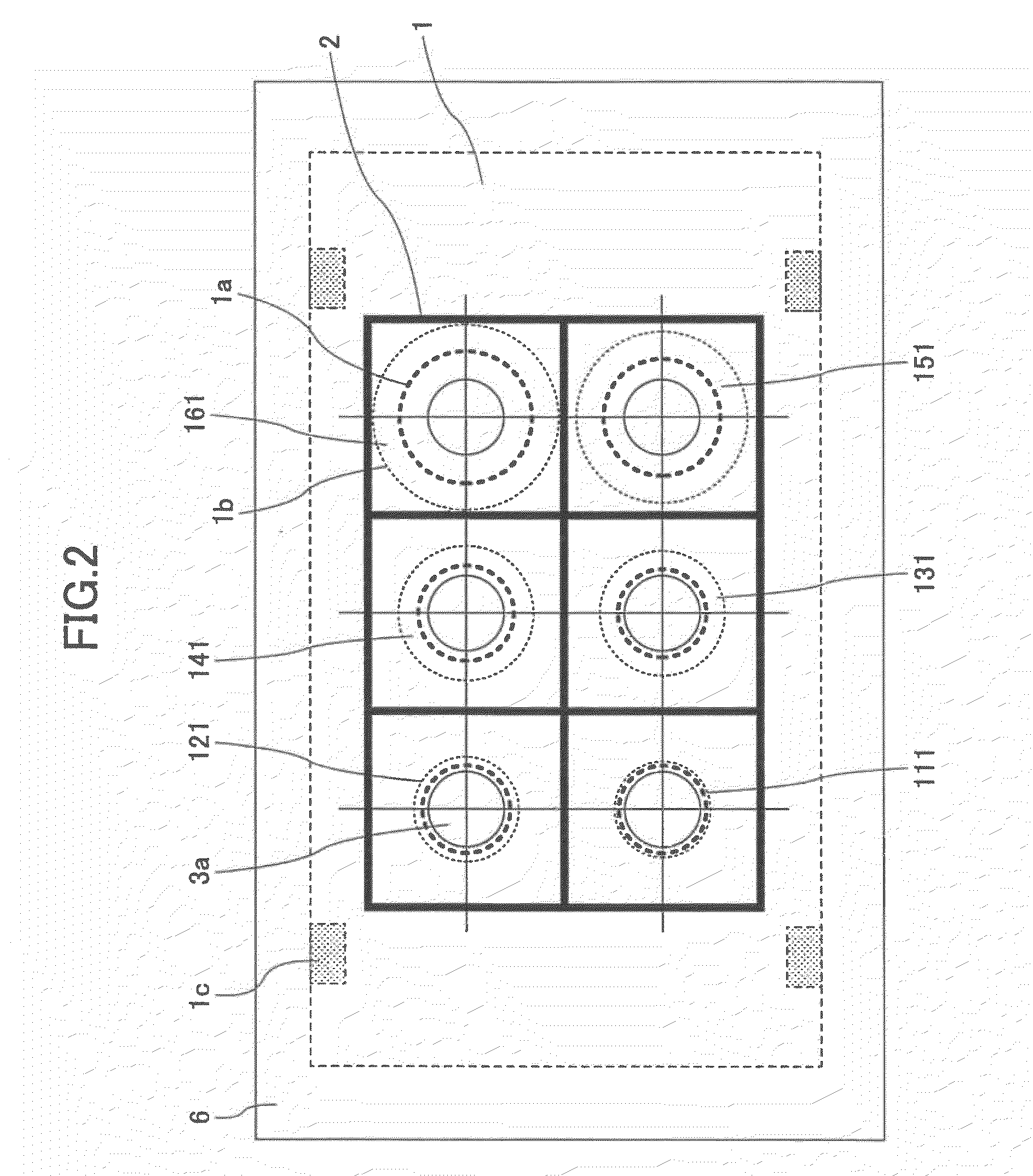
[0050]Since the lens sets 111-161 of the lens array 1 obtain single-eye images of the same subject, the single-eye images include corresponding pixels (corresponding points) representing the same part of the subject. The luminance levels of the corresponding pixels of the single-eye images representing a given part of the subject vary depending on the degrees of focus of the pixels. Take, for example, pixels 9 (corresponding to an eye of the subject) shown in FIG. 7. The luminance levels of the pixels 9 of the single-eye images I1 through I6 are detected. When a pixel is in focus, a dark part becomes darker and a brigh...
third embodiment
[0055]A third embodiment is a variation of the second embodiment. Since lenses (or lens sets) of the lens array are arranged at a predetermined pitch, the direction of a subject viewed from one lens differs from the direction of the subject viewed from another lens. Therefore, single-eye images obtained by the lenses have parallaxes, and the parallaxes change depending on the subject distance. When the subject is at a distant position, the parallaxes become small and can be ignored. Meanwhile, when the subject is at a close position, the parallaxes become large and this makes it difficult to accurately determine the corresponding pixels (or points) in determining a pixel with the extreme luminance level. In this case, it is preferable to determine the corresponding pixels taking into account the parallaxes before determining a pixel with the extreme luminance level. The parallaxes between single-eye images of a subject are obtained by calculating the cross correlation between small ...
PUM
 Abstract
Description
Claims
Application Information