
Solid state lighting assembly

a lighting assembly and solid state technology, applied in the direction of lighting and heating apparatus, lighting support devices, coupling device connections, etc., can solve the problems of inability to effectively package the final lighting system, difficult integration into a functioning system, etc., and achieve efficient configuration and efficient packaging into a lighting fixture

Active Publication Date: 2011-06-09
TYCO ELECTRONICS LOGISTICS AG (CH)
View PDF41 Cites 100 Cited by
  • Summary
  • Abstract
  • Description
  • Claims
  • Application Information

AI Technical Summary

Benefits of technology

[0005]A need remains for a lighting system that may be efficiently packaged into a lighting fixture.

Problems solved by technology

Purchasing the various components from different sources proves to make integration into a functioning system difficult.
This non-integrated approach does not allow the ability to effectively package the final lighting system in a lighting fixture efficiently.

Method used


Image

  • Solid state lighting assembly
  • Solid state lighting assembly
  • Solid state lighting assembly

Examples


Embodiment Construction

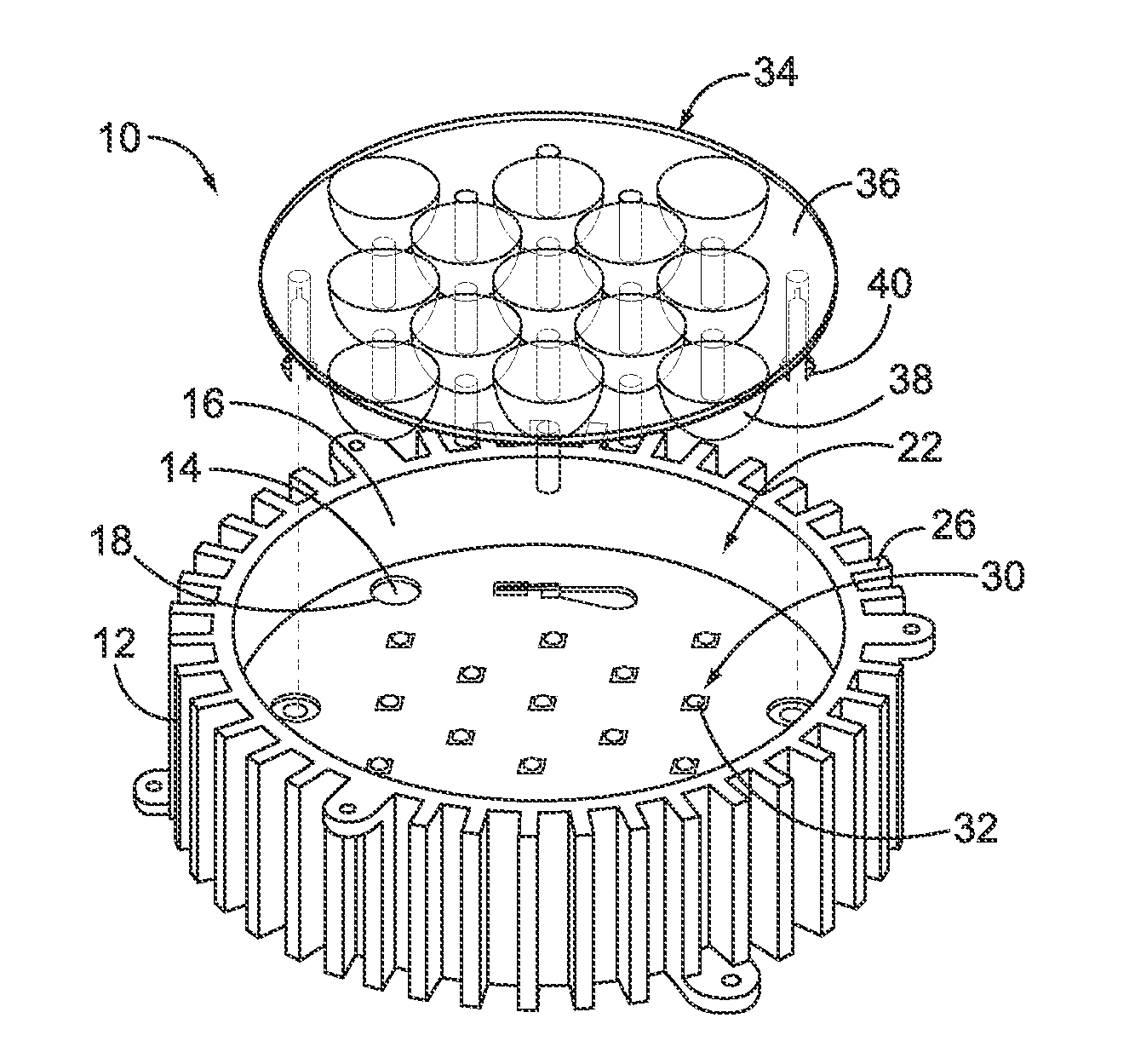
[0016]FIG. 1 is a top perspective view of a solid state lighting assembly 10 formed in accordance with an exemplary embodiment. The assembly 10 represents a light engine for a lighting fixture. In an exemplary embodiment, the assembly 10 is part of a light engine that is used for residential, commercial or industrial use. The assembly 10 may be used for general purpose lighting, or alternatively, may have a customized application or end use.

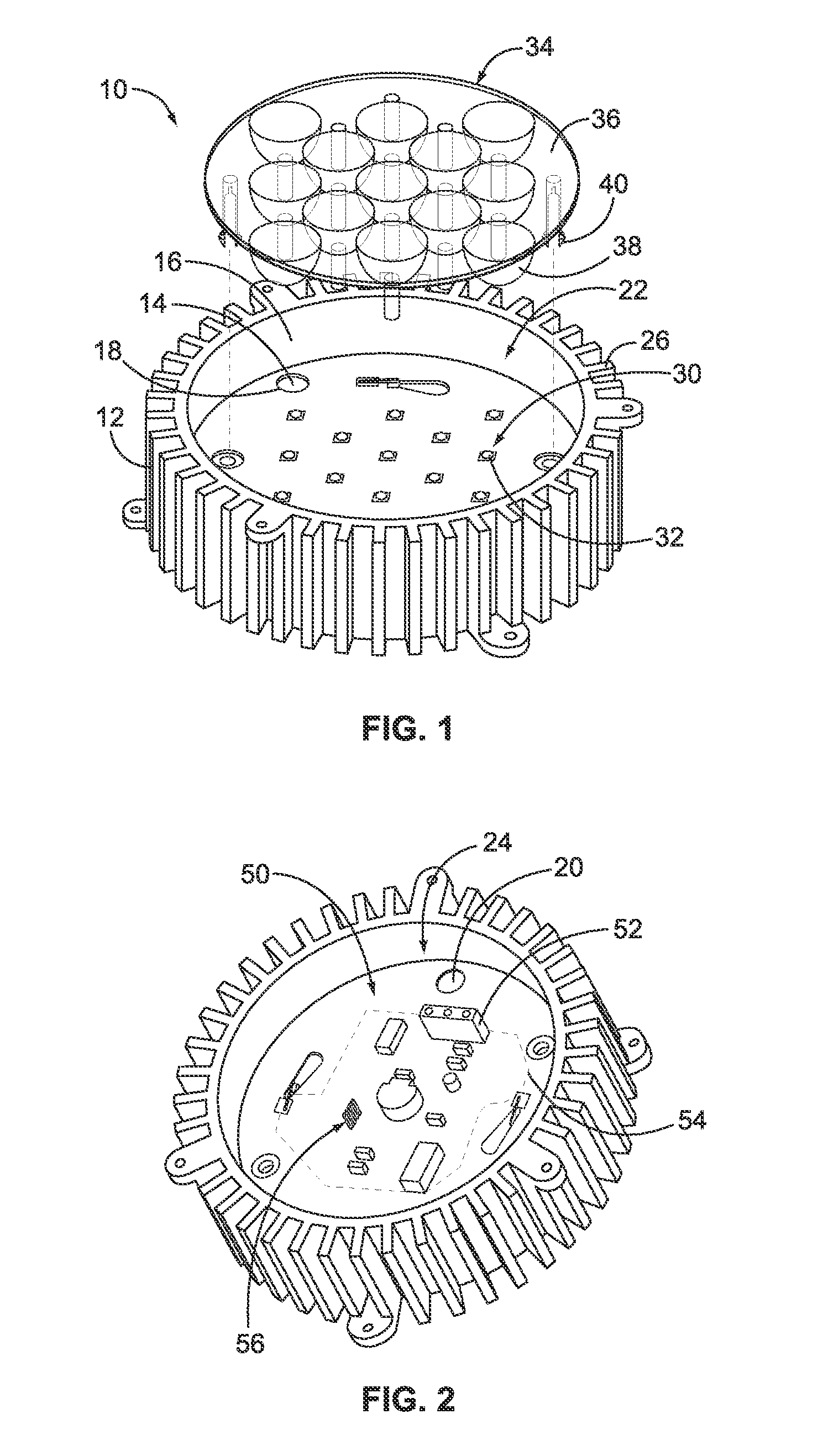
[0017]The assembly 10 includes a socket 12 having a base wall 14 and an outer wall 16 surrounding the base wall 14. The base wall 14 has a first side 18 facing upward and a second side 20 (shown in FIG. 2) facing downward. The outer wall 16 surrounds the base wall 14 to define a first cavity 22 outward of the first side 18 and a second cavity 24 (shown in FIG. 2) outward of the second side 20. In the illustrated embodiment, the base wall 14 is circular in shape and the first cavity 22 is cylindrical in shape. However, it is realized that the base...


PUM


Abstract

A solid state lighting assembly includes a socket having a base wall having a first side and a second side, and a first cavity outward of the first side and a second cavity outward of the second side. Contacts are held by the base wall. The contacts have mating fingers extending into the first and second cavities. A lighting printed circuit board (PCB) is removably positioned within the first cavity with at least one lighting component configured to be powered when electrically connected to corresponding mating fingers of the contacts. The lighting PCB is initially loaded into the first cavity in an unmated position and moved in the first cavity to a mated position. A driver PCB is positioned within the second cavity and is electrically connected to corresponding mating fingers of the contacts. The driver PCB has a power circuit configured to supply power to the lighting PCB when electrically connected to the contacts.

Description

CROSS REFERENCE TO RELATED APPLICATIONS[0001]This Application Relates to U.S. patent application titled LED SOCKET ASSEMBLY, having docket number CS-01138 (958-4048), U.S. patent application titled SOLID STATE LIGHTING SYSTEM, having docket number CS-01139 (958-4049), U.S. patent application titled LED SOCKET ASSEMBLY, having docket number CS-01140 (958-4050), and U.S. patent application titled SOCKET ASSEMBLY WITH A THERMAL MANAGEMENT STRUCTURE, having docket number CS-01141 (958-4051) each filed concurrently herewith, the subject matter of each of which are herein incorporated by reference in their entirety.BACKGROUND OF THE INVENTION[0002]The subject matter herein relates generally to solid state lighting assemblies, and more particularly, to configurable solid state lighting assemblies.[0003]Solid-state light lighting systems use solid state light sources, such as light emitting diodes (LEDs), and are being used to replace other lighting systems that use other types of light sou...

Claims


Application Information

Patent Timeline
IPC IPC(8): F21V9/00F21S4/00
CPCF21V5/007F21V15/01F21V17/002F21V19/045F21V29/004F21Y2101/02F21V29/773F21Y2105/001H01R12/718H01R12/73F21K9/30F21V19/004F21V23/006F21Y2105/00F21K9/20F21V19/04F21Y2105/10F21Y2115/10
Inventor GINGRICH, III, CHARLES RAYMONDMOSTOLLER, MATTHEW EDWARD
Owner TYCO ELECTRONICS LOGISTICS AG (CH)
Features
  • Generate Ideas
  • Intellectual Property
  • Life Sciences
  • Materials
  • Tech Scout
  • Unparalleled Data Quality
  • Higher Quality Content
  • 60% Fewer Hallucinations
Learn More