
Solid state lighting system

a lighting system and solid state technology, applied in the field of solid state lighting systems, can solve the problems of inability to effectively package the final lighting system, inability to effectively integrate into a functioning system, and typical customization of components, so as to achieve efficient configuration and efficient packaging of lighting fixtures

Active Publication Date: 2011-06-09
TYCO ELECTRONICS LOGISTICS AG (CH)
View PDF30 Cites 11 Cited by
  • Summary
  • Abstract
  • Description
  • Claims
  • Application Information

AI Technical Summary

Benefits of technology

[0006]A need remains for a lighting system that may be efficiently packaged into a lighting fixture. A need remains for a lighting system that may be efficiently configured for an end use application.

Problems solved by technology

Purchasing the various components from different sources proves to make integration into a functioning system difficult.
This non-integrated approach does not allow the ability to effectively package the final lighting system in a lighting fixture efficiently.
Another problem with known solid state lighting systems is that the components are typically customized for a particular end use application.
Furthermore, if the needs or functionality of the lighting system were to change, then the entire driver would need to be removed and replaced.
In such situation, the over design of the driver adds to the overall cost of the driver, and the customer may not have need for certain functionality leading the customer to overpay for functionality of the driver that is not needed or wanted.

Method used


Image

  • Solid state lighting system
  • Solid state lighting system
  • Solid state lighting system

Examples


Embodiment Construction

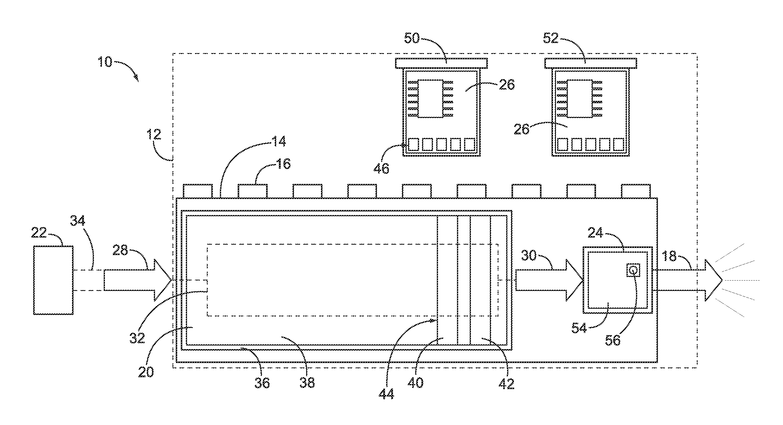
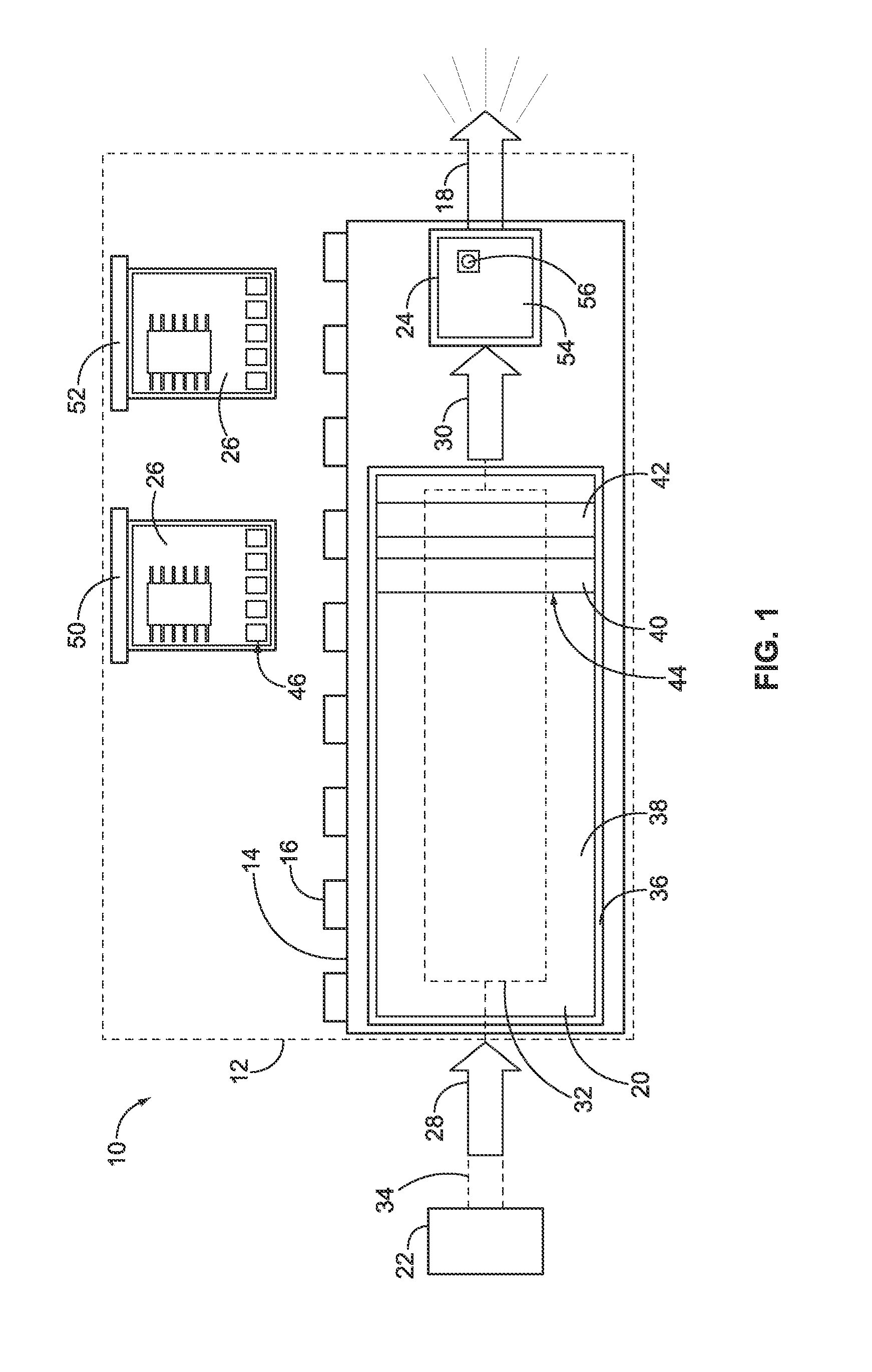
[0020]FIG. 1 is a block diagram of a solid state lighting system 10 for a lighting fixture 12. The lighting fixture 12 generally includes a base 14 that supports the various components of the system 10. The base 14 may include or may constitute a heat sink 16 for dissipating heat generated by the components of the system 10. The system 10 produces light 18 for the lighting fixture 12. In an exemplary embodiment, the lighting fixture 12 is a light engine that is used for residential, commercial or industrial use. The lighting fixture 12 may be used for general purpose lighting, or alternatively, may have a customized application or end use.

[0021]The system 10 includes an electronic driver 20 that receives power from a power source 22, a light emitting diode (LED) subassembly 24 that receives power from the electronic driver 20, and one or more expansion modules 26 that control the electronic driver 20, as described in further detail below. The electronic driver 20 receives a line vol...


PUM


Abstract

A solid state lighting system includes an electronic driver having a power input configured to receive power from a power source and the electronic driver having a power output. The electronic driver controls the power supply to the power output according to a control protocol, and the electronic driver has at least one expansion port having a separable interface. The system also includes a light emitting diode (LED) subassembly having an LED board having at least one LED that receives power from the power output of the electronic driver to power the LED. The system further includes a first expansion module configured to be coupled to the at least one expansion port of the electronic driver having a first functionality affecting the control protocol, and a second expansion module configured to be coupled to the at least one expansion port of the electronic driver having a second functionality affecting the control protocol. The first and second expansion modules are selectively coupled to the at least one expansion port to change the control protocol.

Description

CROSS REFERENCE TO RELATED APPLICATIONS[0001]This application Relates to U.S. patent application titled SOLID STATE LIGHTING ASSEMBLY, having docket number CS-01137 (958-4047), U.S. patent application titled LED SOCKET ASSEMBLY, having docket number CS-01138 (958-4048), U.S. patent application titled LED SOCKET ASSEMBLY, having docket number CS-01140 (958-4050), and U.S. patent application titled SOCKET ASSEMBLY WITH A THERMAL MANAGEMENT STRUCTURE, having docket number CS-01141 (958-4051) each filed concurrently herewith, the subject matter of each of which are herein incorporated by reference in their entirety.BACKGROUND OF THE INVENTION[0002]The subject matter herein relates generally to solid state lighting systems, and more particularly, to configurable solid state lighting systems.[0003]Solid-state light lighting systems use solid state light sources, such as light emitting diodes (LEDs), and are being used to replace other lighting systems that use other types of light sources...

Claims


Application Information

Patent Timeline
Patent Type & Authority Applications(United States)
IPC IPC(8): H05B37/02
CPCH05B37/0245H05B47/175
Inventor RIX, ROBERT D.WEBER, RONALD MARTINGINGRICH, III, CHARLES RAYMONDMOSTOLLER, MATTHEW EDWARDDAILY, CHRISTOPHER GEORGE
Owner TYCO ELECTRONICS LOGISTICS AG (CH)
Features
  • Generate Ideas
  • Intellectual Property
  • Life Sciences
  • Materials
  • Tech Scout
  • Unparalleled Data Quality
  • Higher Quality Content
  • 60% Fewer Hallucinations
Learn More