Optical fiber connector

a technology of optical fiber and connector, applied in the field of optical fiber connector, can solve the problems of not allowing the adhesive to completely surround the adhesive cannot be completely adhered to the sidewall of the optical fiber, and the time-consuming

Inactive Publication Date: 2011-06-09
HON HAI PRECISION IND CO LTD
View PDF7 Cites 4 Cited by
  • Summary
  • Abstract
  • Description
  • Claims
  • Application Information

AI Technical Summary

Problems solved by technology

However, this method costs time and does not permit the adhesive to completely surround the sidewall of the optical fiber.
This may result in the adhesion of

Method used


Image

  • Optical fiber connector
  • Optical fiber connector
  • Optical fiber connector

Examples


first embodiment

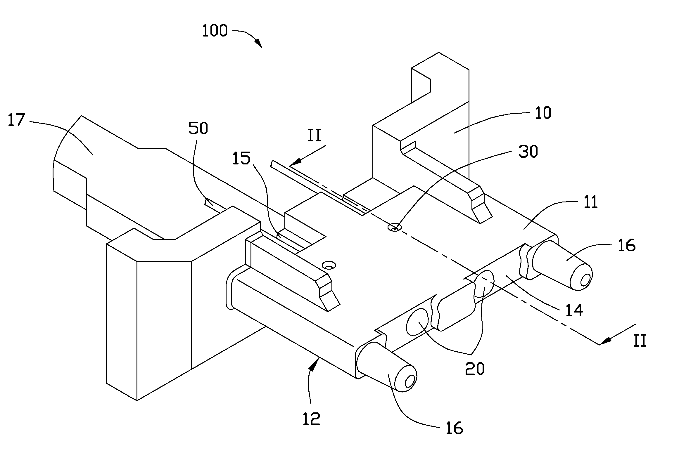
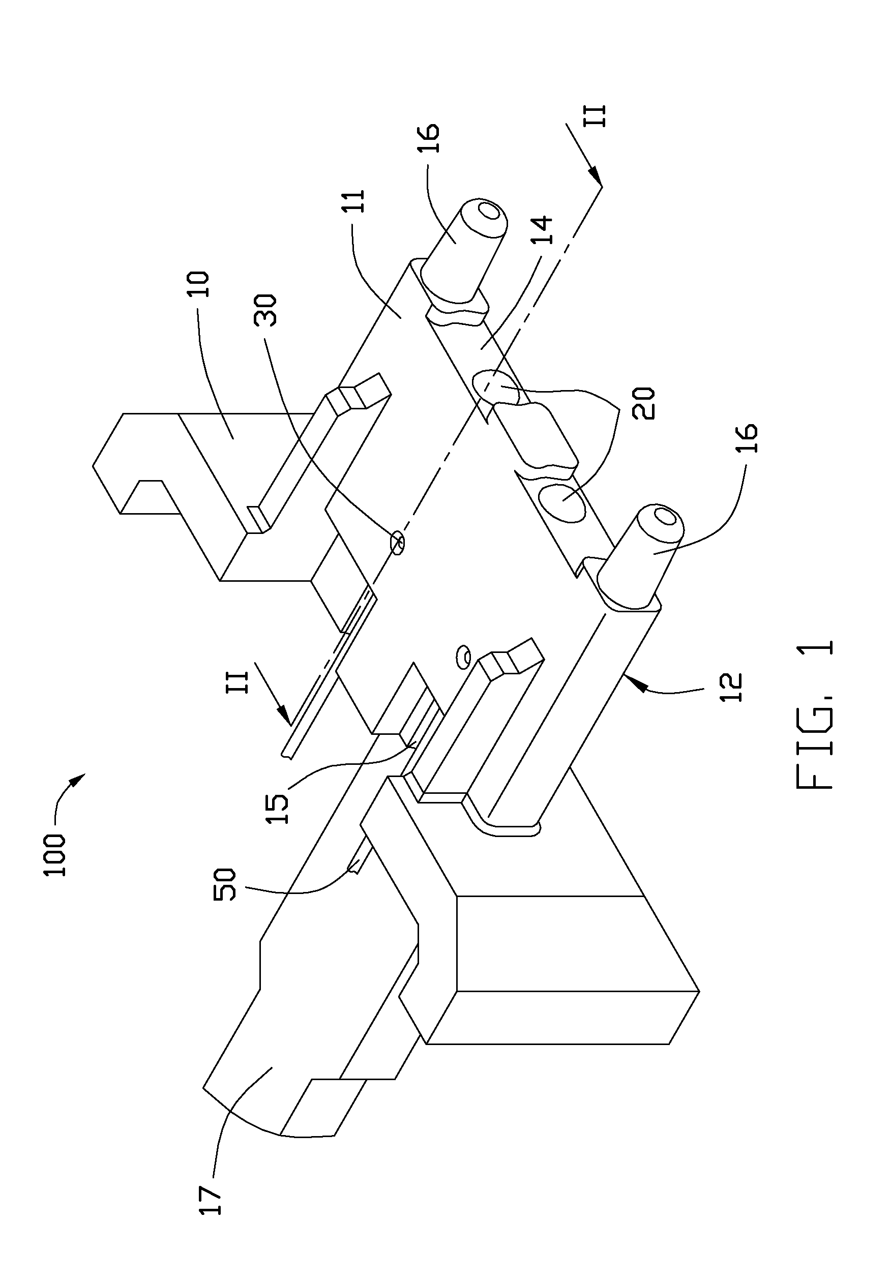
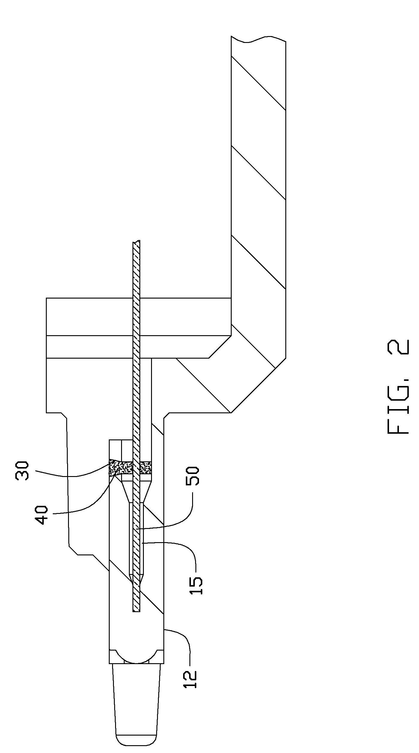
[0012]Referring to FIGS. 1 and 2, an optical fiber connector 100, includes a housing 10 and two lenses 20.

[0013]The housing 10 includes a first surface 11, a second surface 12 opposite to the first surface 11, a third surface 13 and a fourth surface 14 opposite to the third surface 13. The first surface 11 is substantially parallel to the second surface 12. The third surface 13 and the fourth surface 14 respectively connect to the first surface 11 and the second surface 12.

[0014]The housing 10 defines two parallel first blind holes 15. Each of the first blind holes 15 extends from the third surface 13 to the fourth surface 14. The first blind holes 15 are configured for receiving optical fibers 50. In alternative embodiments, the number of the first blind holes 15 may be different and depends on a practical use of the optical fiber connector 100.

[0015]Each lens 20 is integrally formed with the housing 10 on the fourth surface 14 and optical coupled with a corresponding first blind ...

third embodiment

[0021]Referring to FIG. 6, in a third embodiment, corresponding with each first blind hole 320, the optical fiber connector 300 defines more second blind hole 330. Corresponding to each second blind hole 330, the optical fiber connector 300 includes a U-shaped recess 340 on the inner wall of the blind hole 320. The U-shaped recess 340 is in communication with the corresponding second blind hole 330. In alternative embodiments, the U-shaped recess 340 can be omitted.


PUM


Abstract

An exemplary optical fiber connector includes a housing, and two lenses. The housing defines two first blind holes each configured for receiving an optical fiber. The two lenses are formed on the housing and each of the lenses is aligned with a corresponding first blind hole. The two second blind holes are defined on the housing and each of the second blind holes running through the housing to a corresponding first blind hole to allow adhesive to fill between the sidewall of the optical fiber and the inner wall of the blind hole.

Description

BACKGROUND[0001]1. Technical Field[0002]The present disclosure relates to optical fiber connectors.[0003]2. Description of Related Art[0004]Optical fiber connectors typically include a blind hole behind a lens. The blind hole is used to receive an optical fiber. The optical fiber inserted into the blind hole needs to be fixed by adhesive to avoid the optical fiber move in the blind hole. A typical method for adhering the optical fiber in the blind hole is to firstly insert the end of the optical fiber into the blind hole, and then to inject the adhesive at the opening of the blind hole while performing further insertion of the optical fiber into the blind hole to make the adhesive fill between the sidewall of the optical fiber and the inner wall of the blind hole, finally to insert the optical fiber further into the blind hole to accomplish the assemble process of the optical fiber. However, this method costs time and does not permit the adhesive to completely surround the sidewall ...

Claims


Application Information

Patent Timeline
IPC IPC(8): G02B6/36
CPCG02B6/322G02B6/3885G02B6/3861
Inventor YU, TAI-CHERNGYU, SHENG-JUNGLIN, I-THUN
Owner HON HAI PRECISION IND CO LTD
Why Eureka
Try Eureka