Power factor correction circuit with a coil

a technology of power factor and correction circuit, which is applied in the direction of electric variable regulation, process and machine control, instruments, etc., can solve the problems of poor damping effect of the first coil, and achieve the effect of sufficient damping effect, damping effect, and damping response improvement of the first coil

Inactive Publication Date: 2006-02-21
INTERDIGITAL MADISON PATENT HLDG
View PDF17 Cites 0 Cited by
  • Summary
  • Abstract
  • Description
  • Claims
  • Application Information

AI Technical Summary

Benefits of technology

[0010]Although the arrangement of the two inductances in one coil makes the damping effect of the inductance of the first coil poorer than that of a separate coil with an iron core, since there is an interaction via the common core between the two inductances, it has nevertheless been found that the coil with the combined inductances has a completely sufficient damping effect for the switched-mode power supply.
[0011]In one preferred exemplary embodiment, an E/E ferrite core is used as the core and a coil former with chambers is used as the coil former, with the windings of the two inductances being arranged in different chambers. An empty chamber is advantageously arranged in the coil former between the two inductances, and is located in the region of an air gap in the core, so that the one inductance is located above the one inner core limb half, and the other inductance is located above the other inner core limb half of the core. The air gap

Problems solved by technology

Although the arrangement of the two inductances in one coil makes the damping effect of the inductance of the first coil poorer than that of a separate coil with an iron core, since there is an interactio

Method used


Image

  • Power factor correction circuit with a coil
  • Power factor correction circuit with a coil

Examples


Embodiment Construction

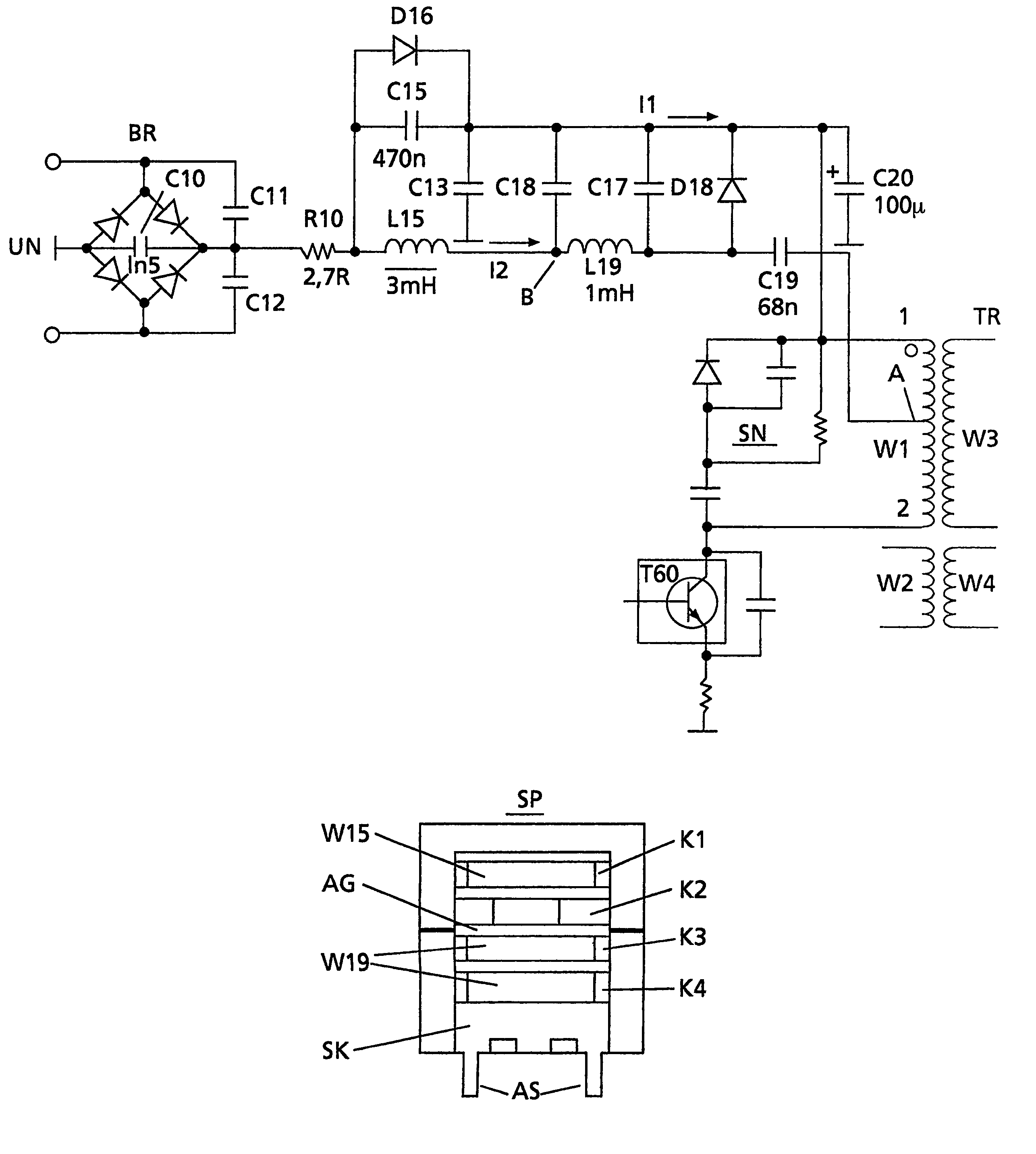
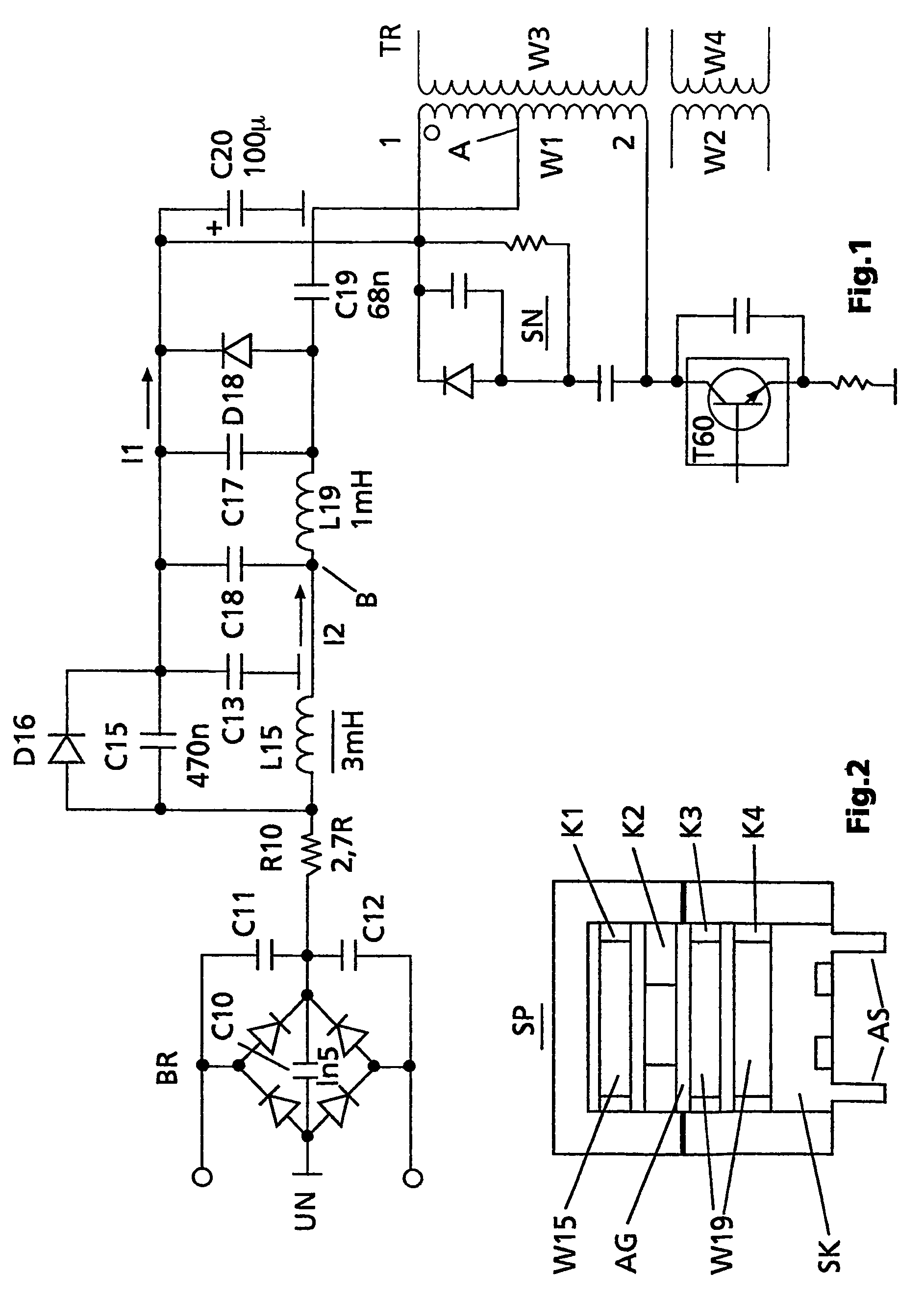
[0016]FIG. 1 shows, in simplified form, a switched-mode power supply with a transformer TR which has a primary winding W1 and secondary windings W2, W3 and W4, as well as a switching transistor T60, which is connected in series with the primary winding W1. The base of the switching transistor T60 is driven in the known manner by a driver circuit (not illustrated), so that, during operation, energy is transmitted from the primary winding W1 to the windings W3 and W4 that are located on the secondary side, as well as to the winding W2, which is arranged on the primary side and is used in particular for supplying the driver circuit. Furthermore, a so-called snubber network SN is arranged in a known manner in parallel with the primary winding W1. Switched-mode power supplies such as these are used, for example, in televisions and, for this power range, are generally in the form of flyback converters.

[0017]On the input side, with respect to one connection UN of the line network, the swit...


PUM


Abstract

The switched-mode power supply according to the invention has a power factor correction circuit, which operates on the principle of a current pump and has a first coil for damping voltage spikes, as well as a second coil for power factor correction. The two inductances are in this case connected in series and are arranged on a coil former and on a common core. In one preferred exemplary embodiment, an E/E ferrite core is used as the core, and a coil former with chambers is used as the coil former, with the windings of the two inductances being arranged in different chambers. An empty chamber, which is located in the region of the air gap in the core, is advantageously arranged between the two inductances. This partially decouples the two inductances by means of the air gap, so that the damping response of the first inductance is better.

Description

[0001]This application claims the benefit under 35 U.S.C. § 365 of International Application PCT / EP02 / 07839, filed Jul. 15, 2002, which claims the benefit of German Patent Application No. 101 35 599.8, filed Jul. 20, 2001.FIELD OF THE INVENTION[0002]The invention is based on a switched-mode power supply with a so-called power factor correction circuit, which is used in order to reduce the harmonic load on the line network from the switched-mode power supply. It relates in particular to a power factor correction circuit which has a current pump with an inductance.BACKGROUND OF THE INVENTION[0003]Switched-mode power supplies produce a highly pulsed load on the line network, which leads to harmonic currents in the line network. This load occurs in particular in the region of the voltage maxima of the sinusoidal network voltage, in which area an energy storage capacitor in the switched-mode power supply is recharged. The harmonic load on the line network can be indicated by a so-called ...

Claims


Application Information

Patent Timeline
IPC IPC(8): G05F1/70H01F5/02H02M7/12H01F17/04H01F27/32H01F37/00H02M1/00H02M1/42H02M3/28
CPCH01F37/00H02M1/4258H01F27/325H01F5/02H01F17/04Y02B70/126Y02B70/10H01F17/043H01F19/00H01F27/027H01F27/38H02M3/28
Inventor ELGERT, ACHIMTHIBAULT, MICHELLOUVEL, JEAN-PAUL
Owner INTERDIGITAL MADISON PATENT HLDG
Why Eureka
Try Eureka