Vibration reduction connecting device for flanges based on particle damping

A vibration connection and damping technology, applied in flange connection, pipe/pipe joint/pipe fitting, through components, etc., can solve the problems of vibration diffusion, difficult vibration reduction treatment, and the installation stability of the liquid outlet pipe does not meet the design requirements. , to achieve the effect of increasing the distribution rate and improving the vibration reduction effect.

Active Publication Date: 2021-11-26
XIAMEN ZHEN-WEI TECH CO LED +1
View PDF10 Cites 0 Cited by
  • Summary
  • Abstract
  • Description
  • Claims
  • Application Information

AI Technical Summary

Problems solved by technology

For example, the liquid outlet pipe connected to the outlet of the water pump through the flange, the vibration from the water pump is easily transmitted to the liquid outlet pipe through the flange connection end, which not only causes the vibration to spread, but also easily leads to the installation stability of the liquid outlet pipe. The design requirements are not met, resulting in frequent leakage problems at the connection nodes of the liquid outlet pipe
However, due to the special structure of the flange, it is extremely difficult to carry out effective vibration reduction treatment.
At present, most of the vibration damping methods of flange connection ends are only damping gaskets between the flanges. In order to ensure the stability of the connection, the connection force between the flanges often forms a rigid extrusion on the vibration damping gaskets. Therefore, the damping effect of the damping gasket between the flanges is basically useless

Method used


Image

  • Vibration reduction connecting device for flanges based on particle damping
  • Vibration reduction connecting device for flanges based on particle damping
  • Vibration reduction connecting device for flanges based on particle damping

Examples


Embodiment 1

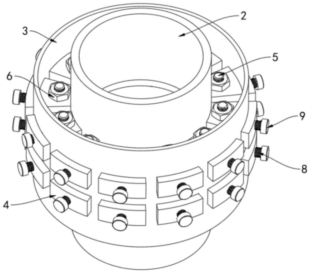
[0039] refer to Figure 1-6 , a vibration-damping connection device for flanges based on particle damping, including

[0040] A set of connecting flanges 1 are fixedly connected to the ends of corresponding workpieces 2;

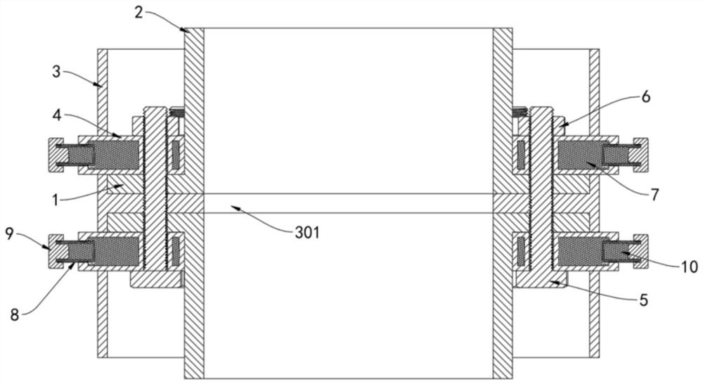
[0041]The fixed pipe fitting 3 is sleeved on the outside of the set of connecting flanges 1, and the middle part of the inner side wall of the fixed pipe fitting 3 is fixed inwardly with a fixed gasket 301 arranged between the set of connecting flanges 1 , the fixed gasket 301 is respectively provided with corresponding first through holes 3011 at positions corresponding to the flange holes of the connecting flange 1, and the fixed pipe fitting 3 is located on both sides of the fixed gasket 301 A plurality of fixing grooves 302 corresponding to the flange holes of the connecting flange 1 are respectively provided;

[0042] A plurality of fixed boxes 4 are detachably installed in the fixed groove 302 respectively, and the inner ends of the fixed boxes 4 are...

Embodiment 2

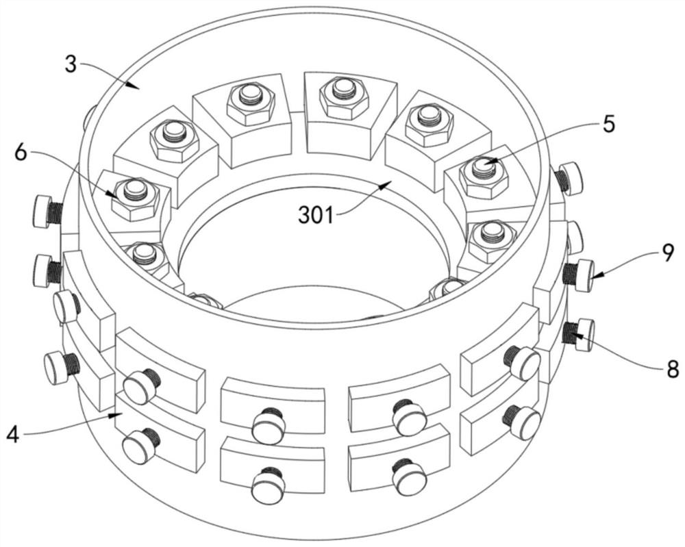
[0056] refer to Figure 7-8 The difference between this embodiment and Embodiment 1 is that the workpiece 2 is a column, and the connecting flanges 1 are respectively affixed to the outer side walls of the ends of the workpiece 2, and the fixing gasket 301 is arranged to be in contact with the The end of the workpiece 2 and the sheet that is compatible with the connecting flange 1.

[0057] It should be pointed out that the realization principle and the technical effect produced by this embodiment are the same as those of the first embodiment. For the sake of brief description, for the parts not mentioned in this embodiment, reference may be made to the corresponding content in the first embodiment.


PUM


Abstract

The invention relates to a vibration reduction connecting device for flanges based on particle damping. The vibration reduction connecting device comprises a group of connecting flanges, a fixing pipe fitting, a fixing box body, a plurality of locking bolts and first damping particles, wherein the group of connecting flanges are fixedly connected to the ends of corresponding workpieces correspondingly; the fixing pipe fitting is arranged on the outer sides of the group of connecting flanges in a sleeving mode, a fixing gasket arranged between the group of connecting flanges in a cushioned mode is fixedly connected to the middle of the inner side wall of the fixing pipe fitting inwards, and a plurality of fixing grooves corresponding to flange holes of the connecting flanges are formed in the positions, on the two sides of the fixing gasket, of the fixing pipe fitting correspondingly; the fixing box body is detachably mounted in the fixing grooves; the locking bolts penetrate through a connecting pipe of the fixing box body, the flange holes of the connecting flanges and first through holes of the fixing gasket correspondingly and then are locked through corresponding locking nuts; and the fixing box body is filled with the first damping particles. According to the vibration reduction connecting device, on the basis that the connecting stability of the connecting flanges is not affected, the vibration reduction effect of the connecting ends of the connecting flanges can be effectively and greatly improved.

Description

technical field [0001] The invention relates to a vibration-damping connection device for flanges based on particle damping, which can be effectively installed in cooperation with the locking flange used for workpiece connection, and can effectively reduce vibration at the joint part of the workpiece while improving the locking effect Effect. Background technique [0002] Flanges are commonly used locking connectors for pipe fittings, rods, columns and other workpieces. Form a clamping lock, so as to effectively connect the workpieces that need to be docked stably into a whole. [0003] Since the connection between the flanges is a rigid connection, it is conducive to the transmission of vibration, so that the vibration of the workpiece at one end is easily transmitted to the workpiece at the other end. For some special working conditions, vibration reduction treatment is often required at the flange connection end. For example, the liquid outlet pipe connected to the out...

Claims


Application Information

Patent Timeline
Patent Type & Authority Applications(China)
IPC IPC(8): F16L55/02F16L55/04F16L23/036
CPCF16L55/02F16L55/041F16L23/036
Inventor 肖望强
Owner XIAMEN ZHEN-WEI TECH CO LED
Why Eureka
Try Eureka