Rechargeable battery

Active Publication Date: 2011-06-09
ROBERT BOSCH GMBH +1
View PDF13 Cites 14 Cited by
  • Summary
  • Abstract
  • Description
  • Claims
  • Application Information

AI Technical Summary

Benefits of technology

[0006]An aspect of the present invention provides a rechargeable battery in which an adhesion section and a non-adhesion section are defined on an

Problems solved by technology

Since the support plate has a very low electric resistance, the heat is not nearly ge

Method used


Image

  • Rechargeable battery
  • Rechargeable battery
  • Rechargeable battery

Examples


Embodiment Construction

[0033]Exemplary embodiments will now be described more fully hereinafter with reference to the accompanying drawings; however, they may be embodied in different forms and should not be construed as limited to the embodiments set forth herein. Rather, these embodiments are provided so that this disclosure will be thorough and complete, and will fully convey the scope of the invention to those skilled in the art.

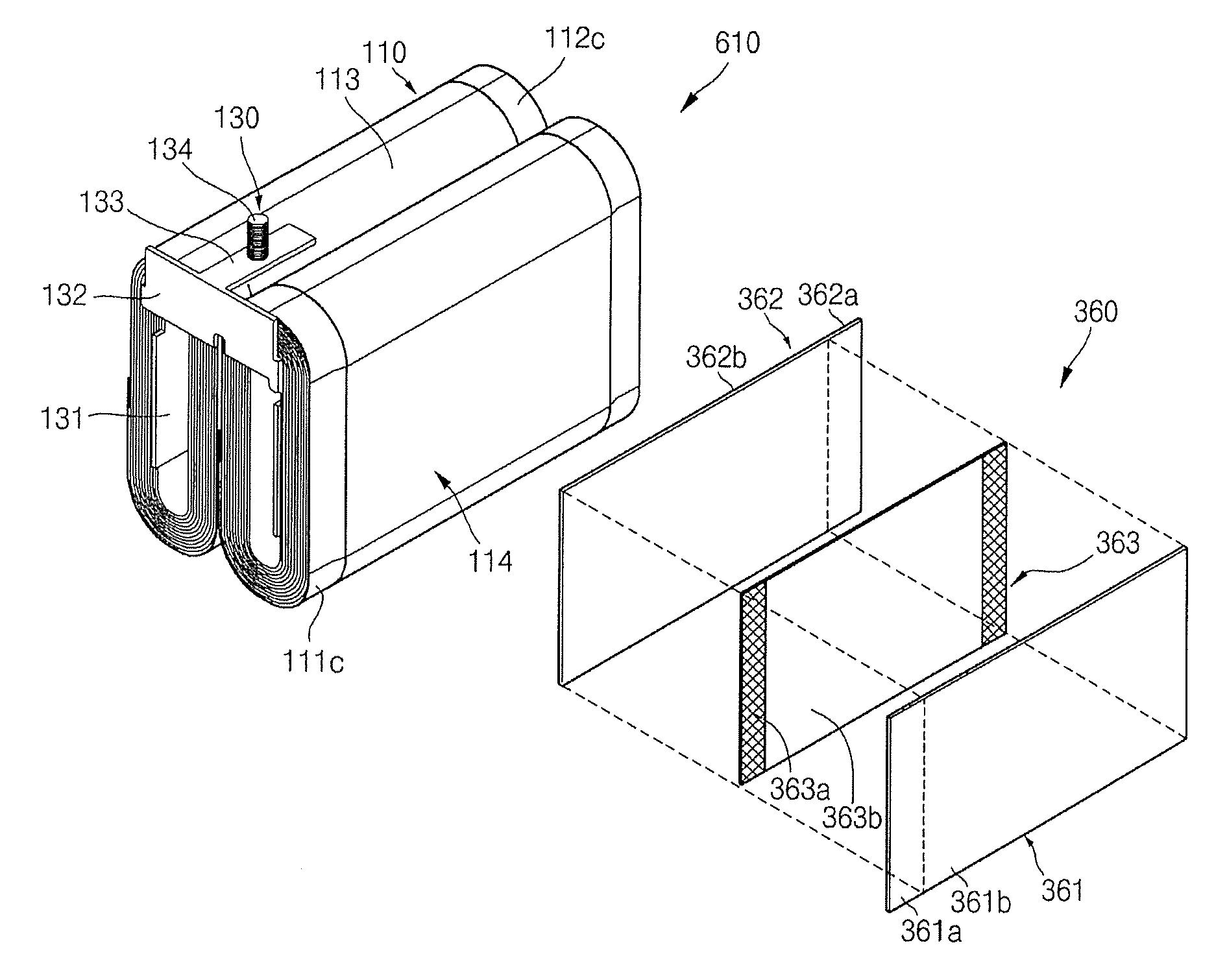
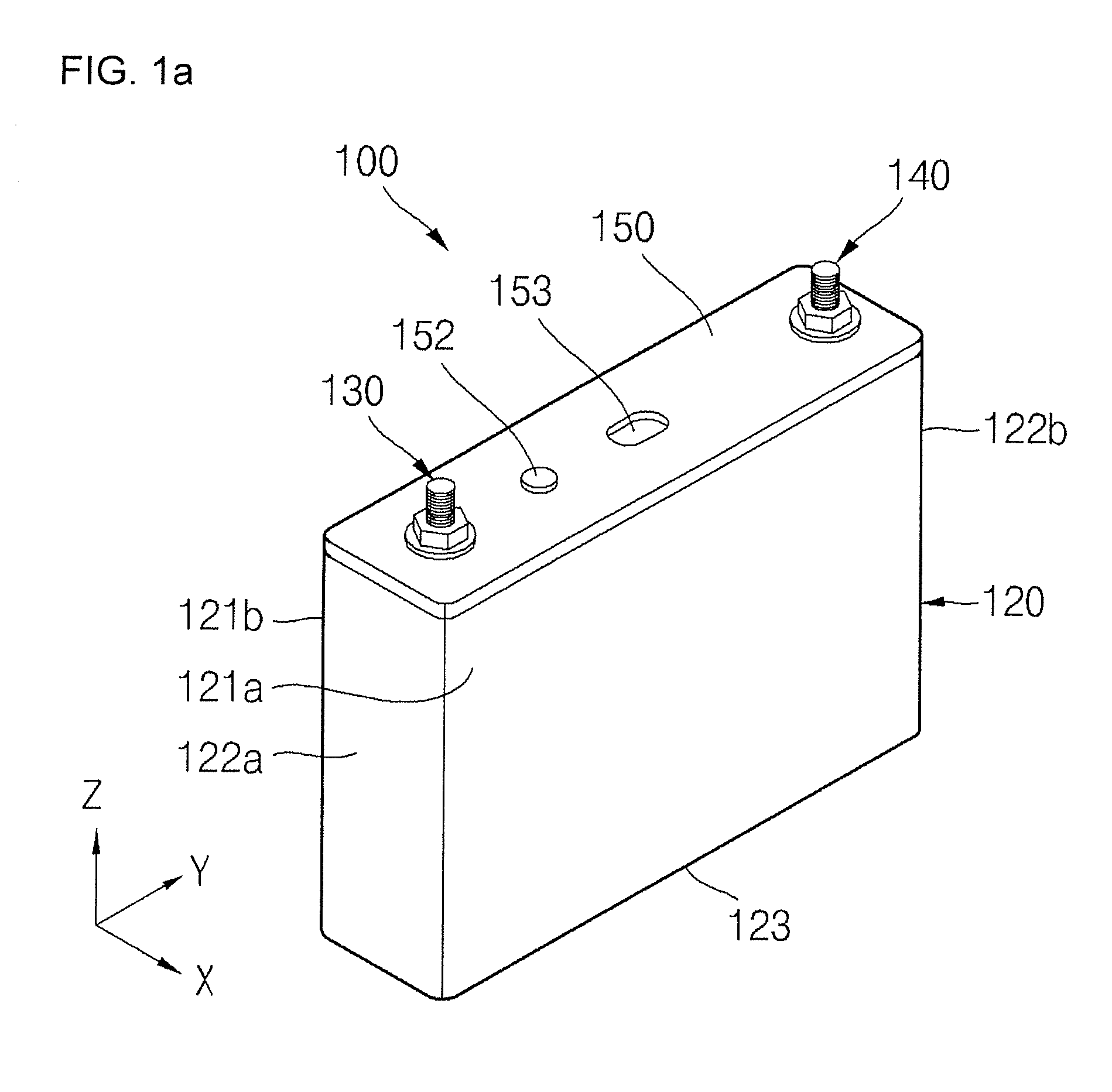
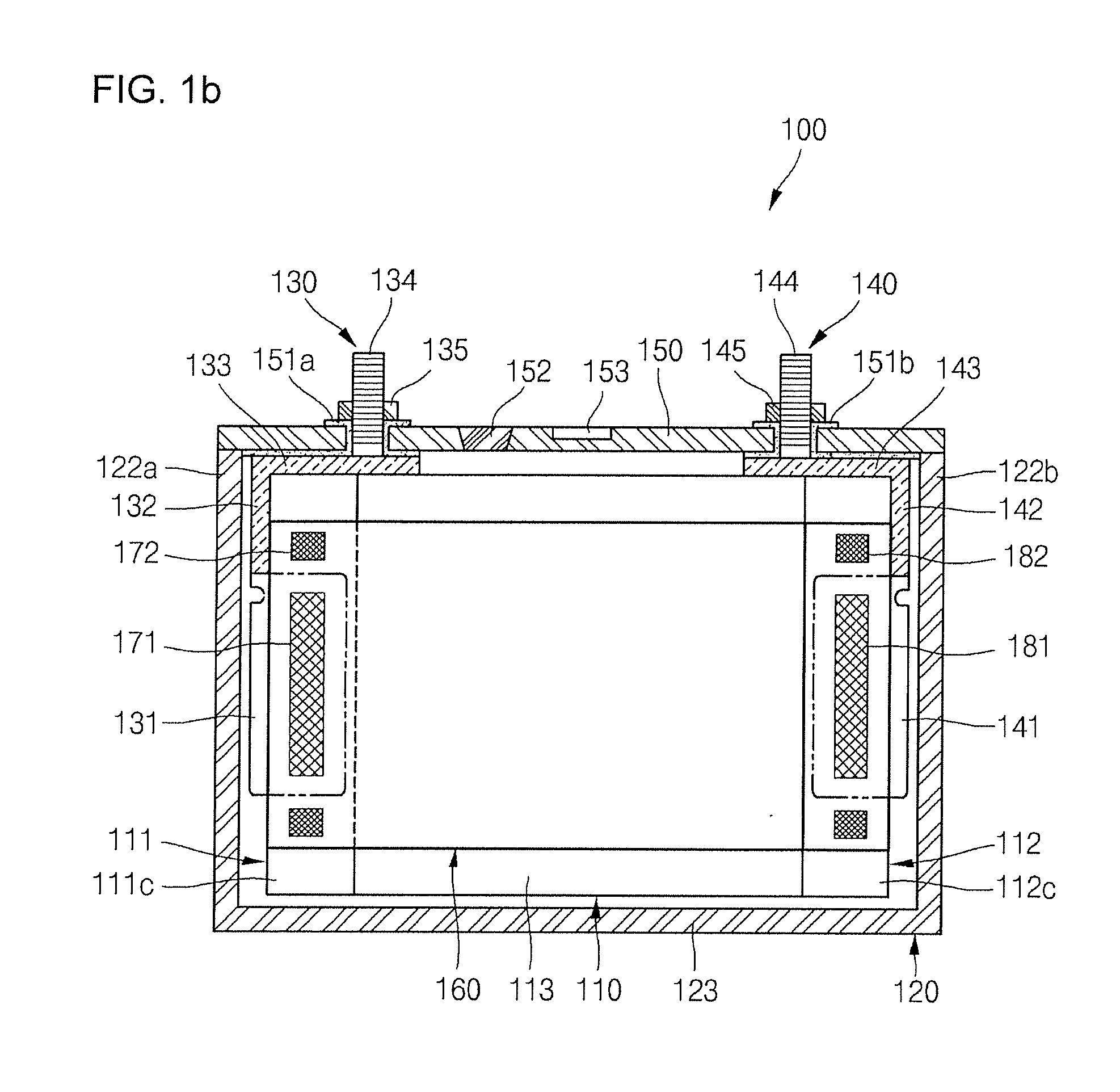
[0034]FIGS. 1A to 1C illustrate perspective, longitudinal sectional, and cross sectional views of a rechargeable battery according to an embodiment, respectively.

[0035]A rechargeable battery 100 according to an embodiment includes an electrode assembly 110, a case 120, a first electrode terminal 130, a second electrode terminal 140, a cap plate 150, and a support plate 160. The case 120 may be a can.

[0036]The electrode assembly 110 includes a first electrode 111, a second electrode 112, and a separator 113. The electrode assembly 110 may be wound in an approximately jelly-roll...


PUM


Abstract

A rechargeable battery includes a case; an electrode assembly housed in the case, wherein the electrode assembly includes a first electrode, a second electrode and a separator between the first electrode and the second electrode; and a support plate between the electrode assembly and the case, the support plate having a first conductive plate electrically coupled to the electrode assembly; wherein an insulation layer is between the first conductive plate and the electrode assembly and wherein an adhesive section is between the insulation layer and the first conductive plate.

Description

CROSS-REFERENCE TO RELATED APPLICATION[0001]This application claims the benefit of U.S. Provisional Application No. 61 / 267,354, filed on Dec. 7, 2009, in the United States Patent and Trademark Office, and claims priority to Korean Patent Application No. 10-2010-0042961, filed on May 7, 2010, in the Korean Intellectual Property Office, the disclosures of which are incorporated herein in their entirety by reference.TECHNICAL FIELD[0002]Embodiments of the present invention relate to a rechargeable battery.BACKGROUND ART[0003]Generally, lithium ion rechargeable batteries are widely used as a power source for small-sized electronic devices such as notebook computers and cellular phones. Furthermore, since the lithium ion rechargeable batteries have high power, high capacity, and light weight when compared to other rechargeable batteries, they are also being used in hybrid and electric automobiles.[0004]Lithium ion rechargeable batteries used as a power source of automobiles should satisf...

Claims


Application Information

Patent Timeline
IPC IPC(8): H01M2/02H01M50/528
CPCH01M2/0207H01M2/0277H01M10/0436H01M10/0431H01M2/347Y02E60/10H01M50/579Y02P70/50H01M50/20H01M10/02H01M50/40B32B15/20
Inventor KWAK, YOONTAIKIM, YONGSAMCHO, KYUWON
Owner ROBERT BOSCH GMBH
Why Eureka
Try Eureka