Brace cap

a brace cap and bracket technology, applied in the field of brace caps, can solve the problems of irritating or injuring the sensitive mouth tissues, no satisfactory solution has been proposed, and the widely accepted approach takes about twenty-four months on average to achieve the effect of success, and achieves the effect of convenient and accurate positioning of the bracket over the brack

Inactive Publication Date: 2011-06-09
ADVANCED ORTHODONTICS & EDUCATION ASSOC LLC
View PDF41 Cites 24 Cited by
  • Summary
  • Abstract
  • Description
  • Claims
  • Application Information

AI Technical Summary

Benefits of technology

[0014]In preferred embodiments, the cap is injection molded as a single plastic piece. Preferably, the plastic has a durometer rating (ASTM D2240) of less than 100 Shore A and preferably less than 90 or 80 or 70 shore, and most preferably between about 10-40 Shore A. The cap also preferably has a thickness of 0.5-5 mm and preferably 1-2 mm. Thickness can vary accord

Problems solved by technology

Although effective, this widely accepted approach takes about twenty four months on average to achieve success.
In use, current orthodontic braces present a particular problem at the distal

Method used


Image

  • Brace cap
  • Brace cap
  • Brace cap

Examples


example 1

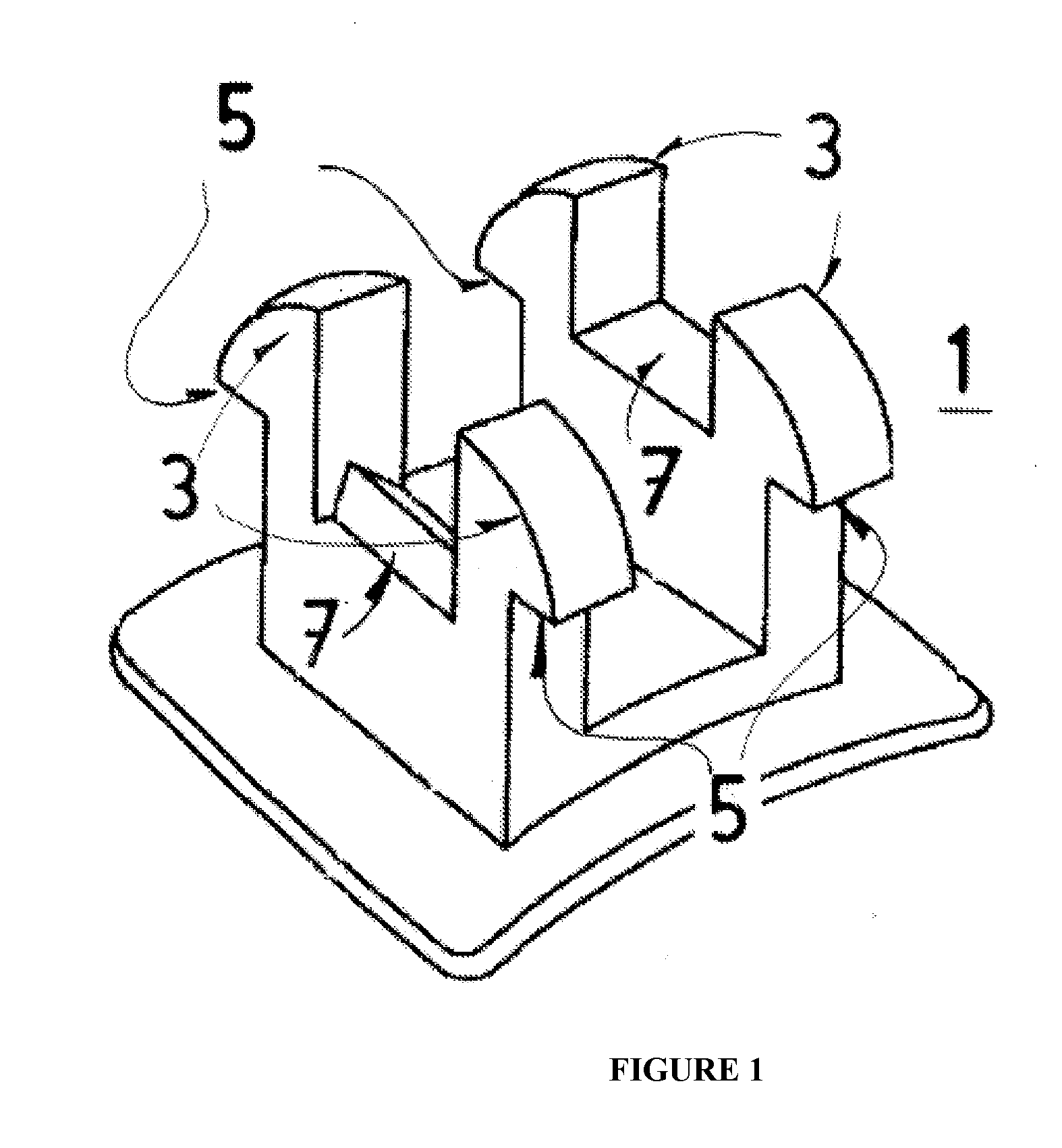
[0021]A typical orthodontic bracket 1 is shown in FIG. 1, wherein a pair of rails 3 are shown, along with a slot 7 into which the archwire (not shown) fits. Recessions 5 are typically found on a bracket into which rubber bands fit, thus holding the archwire in place.

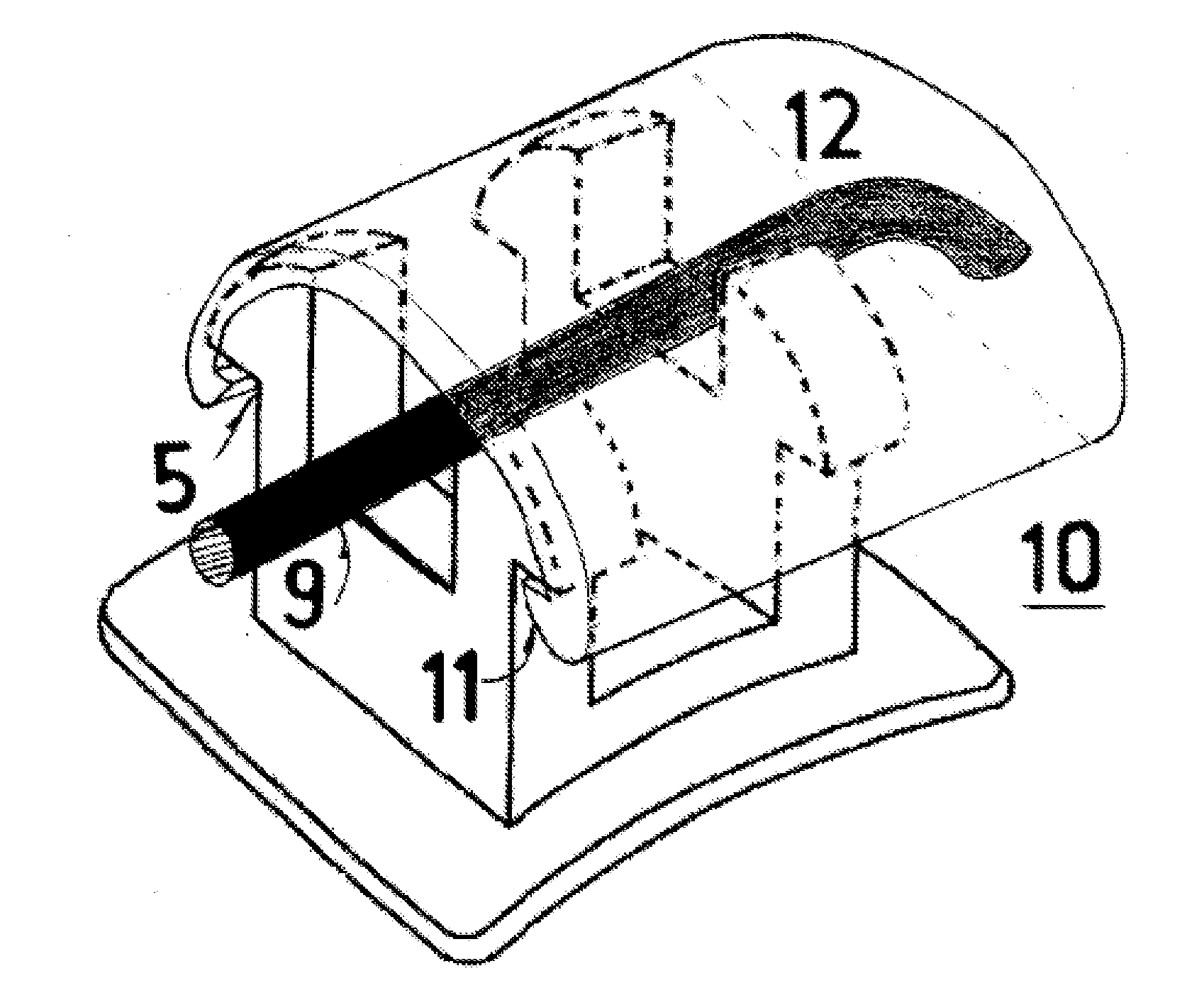
[0022]A brace cap 10 is shown fitting on a typical bracket in FIG. 4. Generally speaking the cap has an open end and an open bottom, to accommodate the teeth and braces. However, the top and other end are closed. The exterior surface thus partially encloses an interior hollow.

[0023]More particularly, archwire 9 fits into the slot 7 (not labeled) of a bracket (not labeled) and fits into the hollow 12 or space in the end of brace cap 10. Protrusions 11 fit into the recessions 5 on bracket 1 (not labeled), thus providing a snap fit, but obviously these can be reversed, the cap providing the recessions and the bracket having protrusions. The same bracket is show from the open end in FIG. 5 which more clearly illustrates prot...


PUM


Abstract

Vibrating dental devices and accessories are provided, including a unique snap fit dental plate and vibrator connection; risers for adjusting the thickness of a dental plate; a pointer or wand that can be clamped onto a dental plate to reach even severely misaligned teeth; a cushioned dental plate having a non-Newtonian fluid therein that allows conformation of the cushion to the dentition, but hardens on use to allow the transmission of vibration to the teeth. Accessories such as carrying cases and docking stations are also provided.

Description

PRIOR RELATED APPLICATIONS[0001]This application claims priority to U.S. Provisional Application Ser. No. 61 / 250,343, filed on Oct. 9, 2009, which is incorporated herein in its entirety.FEDERALLY SPONSORED RESEARCH STATEMENT[0002]Not applicable.REFERENCE TO MICROFICHE APPENDIX[0003]Not applicable.FIELD OF THE INVENTION[0004]The invention relates to a brace cap that fits over the end of orthodontic braces, which protects the patient from the arch wire protruding therefrom.BACKGROUND OF THE INVENTION[0005]Orthodontics is a dental specialty that treats malocclusion through the movement of teeth as well as control and modification of facial growth. This process is usually accomplished by using a continuous mechanical force to induce bone remodeling, thereby enabling the teeth to move to a better position. In this approach, orthodontic appliances provide a continuous static force to the teeth, usually via an archwire connected to brackets affixed to each tooth. As the teeth slowly move d...

Claims


Application Information

Patent Timeline
IPC IPC(8): A61C7/28
CPCA61C7/30A61C7/125
Inventor LEVENS, LAWRENCE J.
Owner ADVANCED ORTHODONTICS & EDUCATION ASSOC LLC
Why Eureka
Try Eureka