Apparatus and method for scalable power distribution

a power distribution and applicator technology, applied in the direction of insulated conductors, coupling device connections, cables, etc., can solve the problems of unscalable systems, undesirable scheduled outages, and failure to configure the correct size or quantity of circuits and corresponding circuit breakers of each panel board or other power distribution unit, so as to achieve safe installation and removal

Active Publication Date: 2011-06-09
SCHNEIDER ELECTRIC IT CORP
View PDF63 Cites 66 Cited by
  • Summary
  • Abstract
  • Description
  • Claims
  • Application Information

AI Technical Summary

Benefits of technology

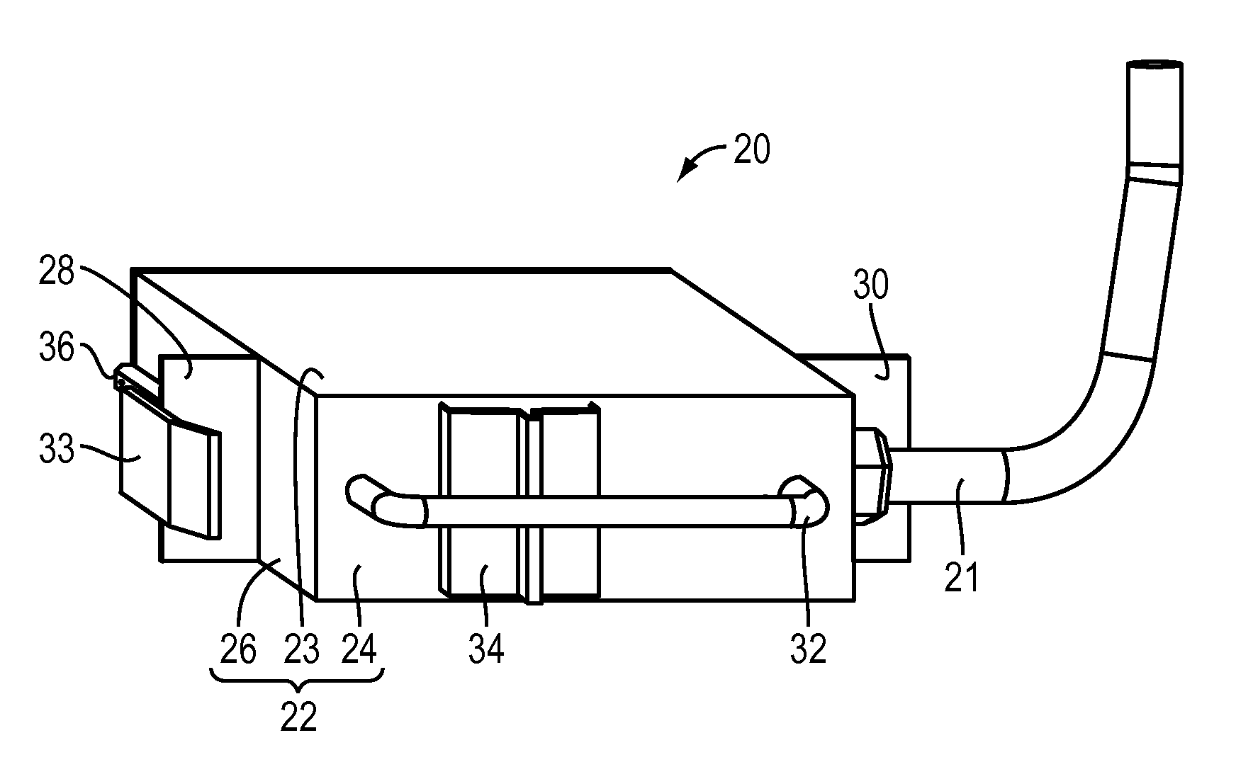
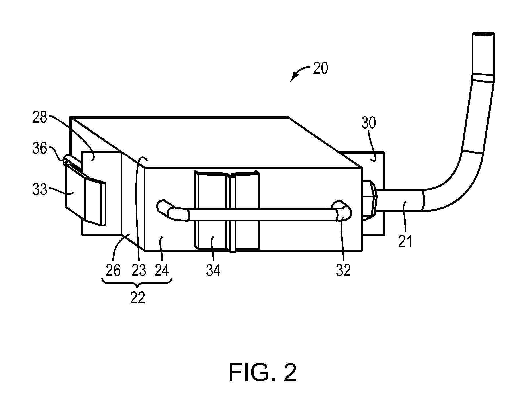
[0008]In one or more embodiments, the invention provides a modular, scalable power distribution system that provides tap modules that may be safely installed and removed without disrupting other electrical circuits connected to the power distribution unit. As a result, in some embodiments, the invention provides for a scalable power distribution apparatus that provides flexibility to meet the changing electrical needs of a facility such as a data center. For example, in some embodiments, a user can employ a rack mounted power distribution unit to customize the location of the connection for newly added lo...

Problems solved by technology

Problems with these approaches include the fact that the installation or removal of a circuit breaker from the panel board or power distribution unit requires that a skilled individual (i.e., an electrician) perform the installation or removal in close proximity to energized electrical circuits which may include exposed electrical connections ...

Method used


Image

  • Apparatus and method for scalable power distribution
  • Apparatus and method for scalable power distribution
  • Apparatus and method for scalable power distribution

Examples


Embodiment Construction

[0028]This invention is not limited in its application to the details of construction and the arrangement of components set forth in the following description or illustrated in the drawings. The invention is capable of other embodiments and of being practiced or of being carried out in various ways. Also, the phraseology and terminology used herein is for the purpose of description and should not be regarded as limiting. The use of “including,”“comprising,” or “having,”“containing”, “involving”, and variations thereof herein, is meant to encompass the items listed thereafter and equivalents thereof as well as additional items.

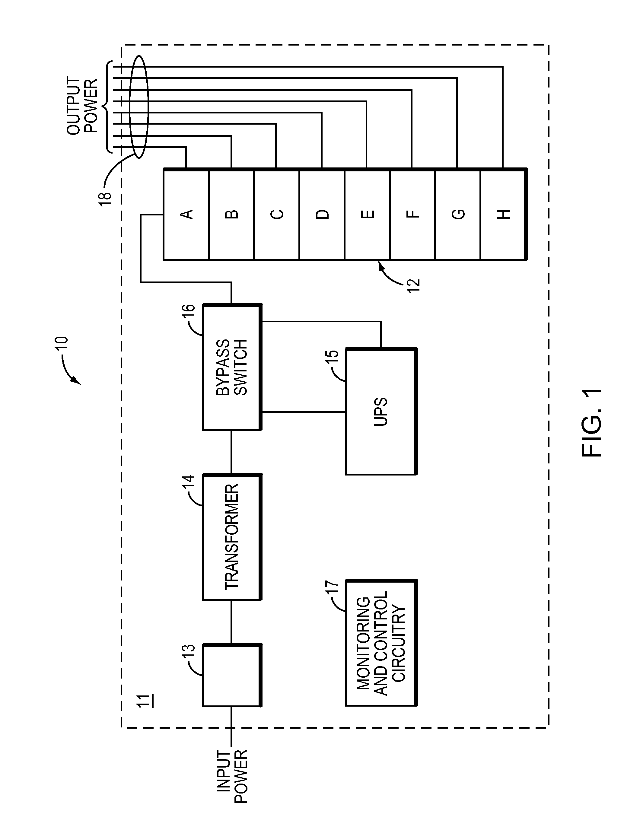
[0029]Each of commonly-owned U.S. patent application Ser. No. 11 / 766,504, filed Jun. 21, 2007, entitled APPARATUS AND METHOD FOR SCALABLE POWER DISTRIBUTION and U.S. patent application Ser. No. 11 / 455,227, filed Jun. 16, 2006, entitled APPARATUS AND METHOD FOR SCALABLE POWER DISTRIBUTION describe embodiments of modular, scalable power distribution systems that ...


PUM

PropertyMeasurementUnit
Lengthaaaaaaaaaa
Poweraaaaaaaaaa

Abstract

In one aspect, the invention provides a system for power distribution. According to some embodiments, the system includes a rack mountable power distribution unit including a housing having a first end and a second end, the housing also including an outer wall defining a cavity within the housing, and fastening elements configured to allow the housing to be mounted within an electrical equipment rack. In accordance with these embodiments, the outer wall of the housing includes an opening extending linearly between the first end and the second end of the housing and a plurality of electrical conductors located within the cavity and oriented linearly between the first end and the second end. In accordance with further embodiments, the system includes a tap module including a plurality of contacts extending therefrom wherein each of the plurality of contacts is configured to be inserted into the opening before engaging one of the plurality of electrical conductors within the cavity, respectively.

Description

BACKGROUND OF INVENTION[0001]1. Field of Invention[0002]Embodiments of the invention relate generally to electrical power distribution equipment. More specifically, at least one embodiment relates to an apparatus and a method for scalable power distribution.[0003]2. Discussion of Related Art[0004]Centralized data centers for computer, communications and other electronic equipment have been in use for a number of years. More recently, with the increasing use of the Internet, large scale data centers that provide hosting services for Internet service providers (“ISPs”), application service providers (“ASPs”) and Internet content providers are becoming increasingly popular. Typical centralized data centers contain numerous racks of equipment that require power, cooling and connections to communication facilities.[0005]In general, centralized data centers have a power distribution system configured to avoid power outages because the data centers include a high percentage of critical loa...

Claims


Application Information

Patent Timeline
IPC IPC(8): H01R13/648H01R13/66H01R43/00
CPCY10T29/49826Y10T29/49117H01B7/30H01R25/142H01R25/003H02B1/056
Inventor SPITAELS, JAMES S.JANSMA, MICHAELJOHNSON, PATRICK RILEYZIEGLER, WILLIAM
Owner SCHNEIDER ELECTRIC IT CORP
Why Eureka
Try Eureka