Eureka AIR delivers breakthrough ideas for toughest innovation challenges, trusted by R&D personnel around the world.

Method for Leveling Parts in a Roller Leveling Machine

Active Publication Date: 2011-06-16
ARKU MASCHENBAU
View PDF3 Cites 6 Cited by
  • Summary
  • Abstract
  • Description
  • Claims
  • Application Information

AI Technical Summary

Benefits of technology

[0018]The present invention is therefore based on a goal of providing a method for leveling parts in a part leveling machine in which the disadvanages cited above are avoided and which leads to considerable improvement in the results achieved for the leveled parts.
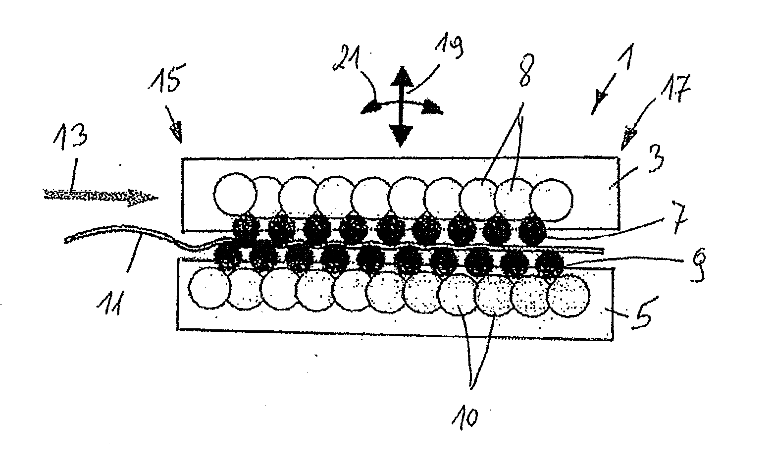
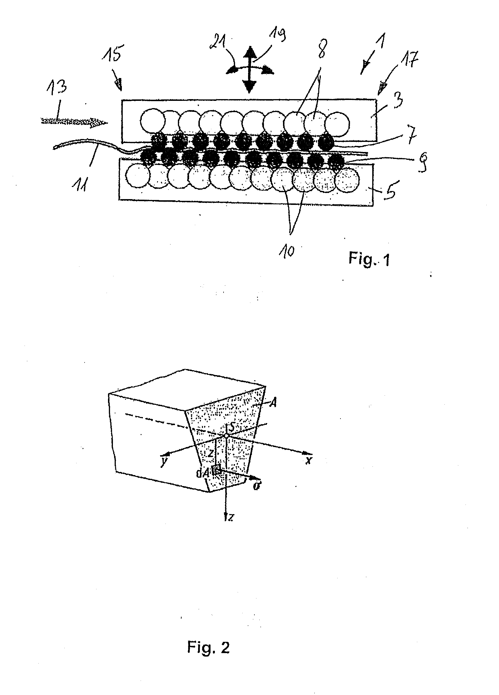
[0028]As a result of the shifting of the block, i.e. because the leveling rollers are shifted all together in a block, the back-and-forth bends produced in the machine become highly dependent on each other, in contrast to the situation which exists when the leveling rollers are adjusted individually. The blockwise shift brings about, so to speak, a uniform decrease in the degree of back-and-forth bending from the infeed side to the outfeed side of the machine.

Problems solved by technology

A disadvantage of leveling machines is that the leveling gap does not remain constant during the leveling process; the gap in fact changes in accordance with the elastic behavior of the mechanical components.
The leveling process is especially difficult in the case of parts which do not have a rectangular contour but have instead round contours and / or large cut-out areas.
This is time-consuming and therefore also expensive.
Because the contours of the parts for part leveling can differ widely from each other, as explained above, basing the process on the thickness of the material alone is not sufficient.

Method used


Image

  • Method for Leveling Parts in a Roller Leveling Machine
  • Method for Leveling Parts in a Roller Leveling Machine
  • Method for Leveling Parts in a Roller Leveling Machine

Examples


Embodiment Construction

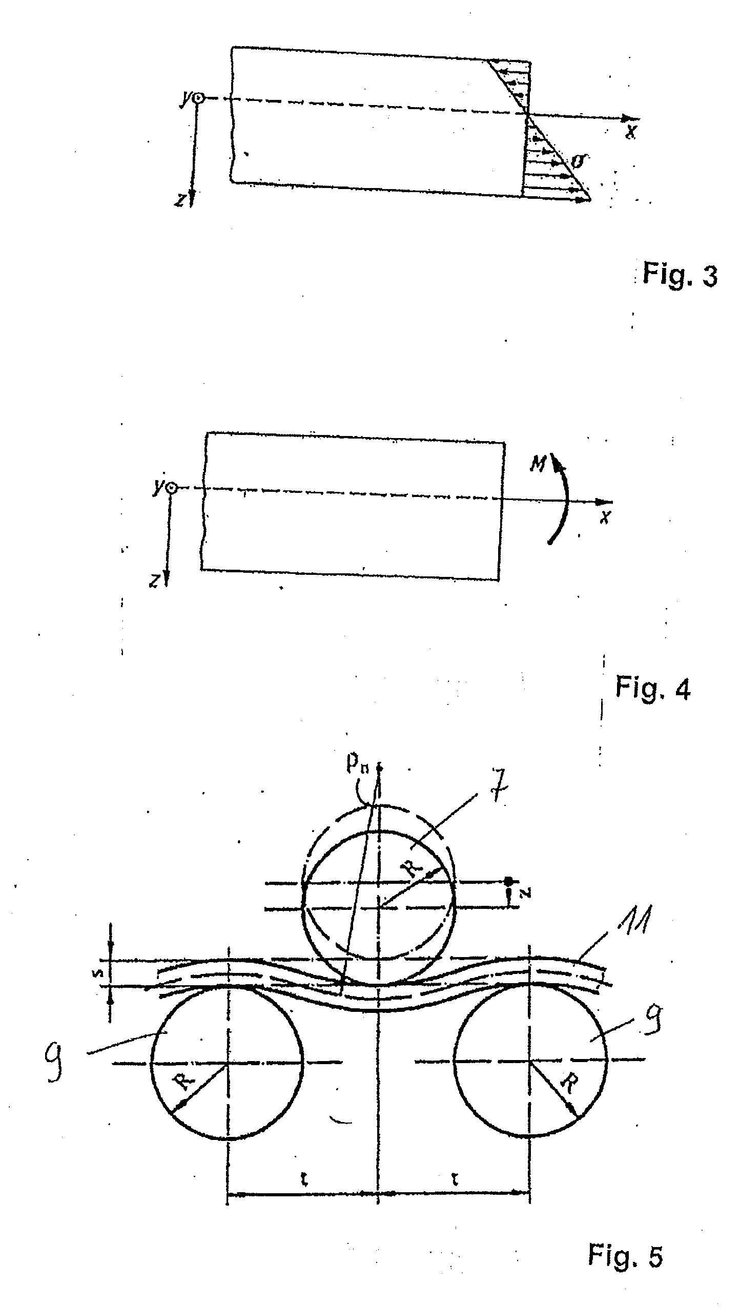
[0039]FIG. 6 shows a part 11 to be leveled, which has here a bridge-like contour; that is, it has a rectangular shape with a semicircular cutout with radius R in the middle. The part 11 has the thickness s. The leveling triangle in the case of the example of FIG. 6 measures 65 mm, which means that the dimension 2t equals 65 mm. In the example, therefore, the side length ΔX of the partial area component of the part 11 to be leveled is selected so that it is equal to the dimension 2t, that is, to the length of the leveling triangle.

[0040]The width of the part 11 is 400 mm at both the front and the back edge, and its total length, which is measured from right to left, opposite the direction of travel of the part 11 to be leveled through the part leveling machine, as indicated by arrow 13, is 800 mm. Width b is measured is the middle of each partial area, which is shown by the dash-dot line.

[0041]Column 1 of the table of FIG. 7 gives the positions of the leveling triangles. The numbers ...


PUM

PropertyMeasurementUnit
Massaaaaaaaaaa
Shapeaaaaaaaaaa
Elasticityaaaaaaaaaa

Abstract

A method for leveling parts in a roller leveling machine, which includes an upper and a lower roller frame, and in which upper and lower leveling rollers are each arranged in a separate leveling roller block, at least one of the leveling roller blocks being variable in its position and angle so that the leveling gap can be adjusted, wherein at least one leveling gap setting device is arranged at the infeed side and at the outfeed side of the leveling machine, and an automatic leveling gap control is provided to set the leveling gap. The method includes determining, for each leveling triangle of the roller leveling machine, an offset value based on the thickness, width, and bending moment of the part to be leveled and characteristics of the leveling machine including a max deflection of the roller frame, and readjusting a setting device of the leveling gap as a function of the leveling triangles mapped onto the part to be leveled as it moves through the leveling gap.

Description

BACKGROUND OF THE INVENTION[0001]1. Field of Invention[0002]The present invention pertains to a method for leveling parts in a roller leveling machine.[0003]2. Discussion of Background Art[0004]Roller leveling is a bending method in which certain tools, called leveling rollers, bend the material to be leveled back and forth. The machines used to carry out the method are called leveling machines. In these machines, the material to be leveled is passed between two opposing rows of leveling rollers, which are offset from each other. The upper and lower rows of leveling rollers are offset from each other in such a way that the rollers of one row nest in the intermediate spaces between the opposing rollers. The depth to which the rollers nest in these intermediate spaces and the geometry of the leveling rollers themselves determine the degree of the back-and-forth bending, which must occur in the partially plastic state. The greatest degree of back-and-forth bending occurs on the infeed ...

Claims


Application Information

Patent Timeline
IPC IPC(8): B21D3/02B21D1/02
CPCB21F1/02B21D3/05
Inventor BRAEUTIGAM, HORSTKHIM, GERALD
Owner ARKU MASCHENBAU
Why Eureka
Eureka Blog
Learn More