
Surface texture measuring device

a surface texture and measuring device technology, applied in the direction of measurement devices, mechanical roughness/irregularity measurements, instruments, etc., to achieve the effect of efficient measurement of surface roughness of a measurement fa

Active Publication Date: 2011-06-16
MITUTOYO CORP
View PDF5 Cites 8 Cited by
  • Summary
  • Abstract
  • Description
  • Claims
  • Application Information

AI Technical Summary

Benefits of technology

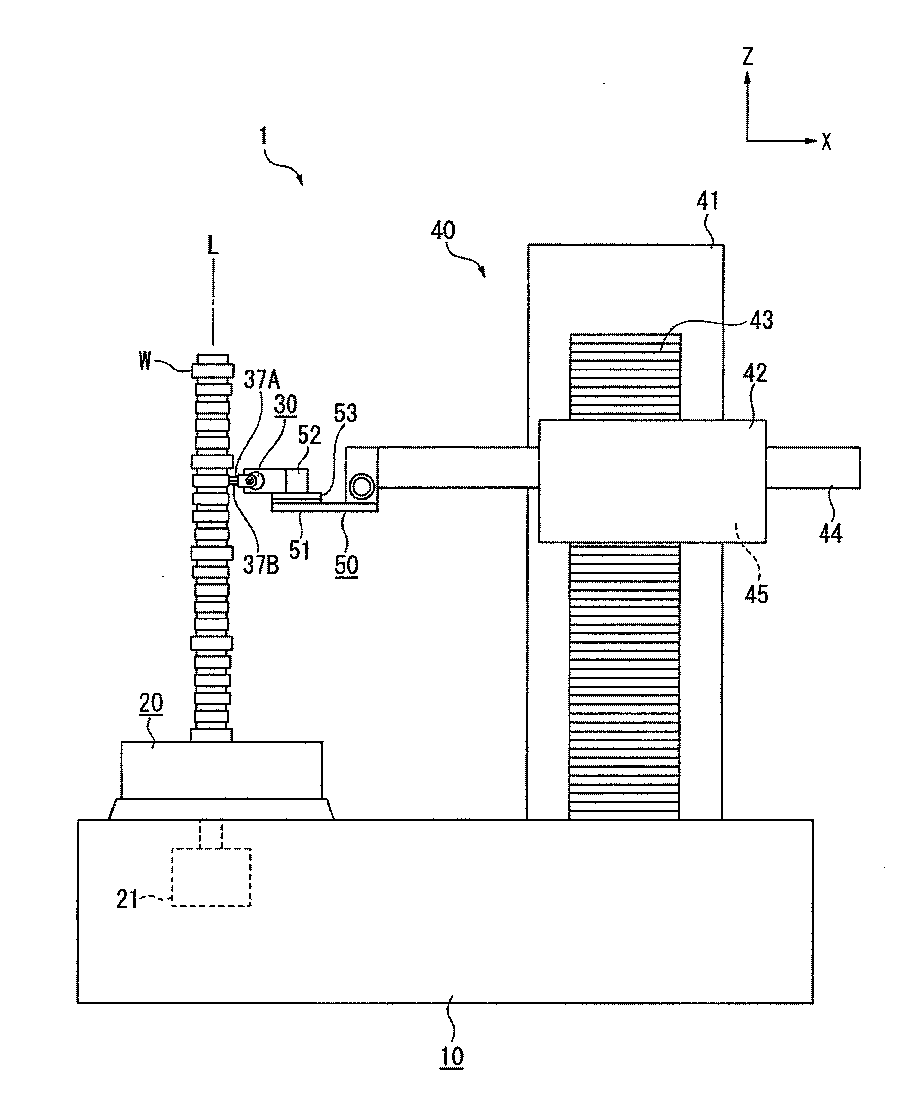
[0009]Exemplary embodiments of the present invention provide a surface texture measuring device that can efficiently measure surface roughness of a measurement face with a large eccentricity amount, etc., such as a cam.
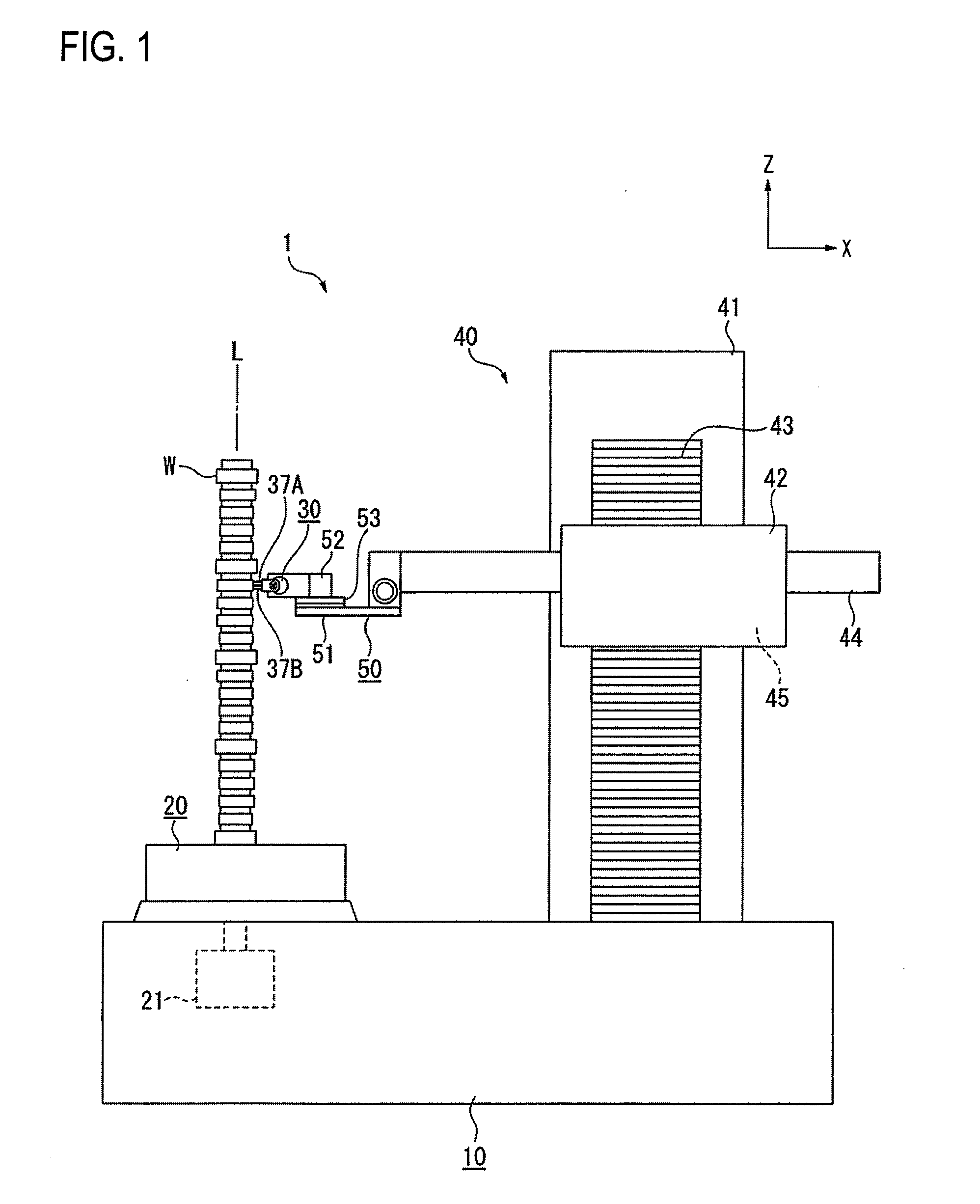
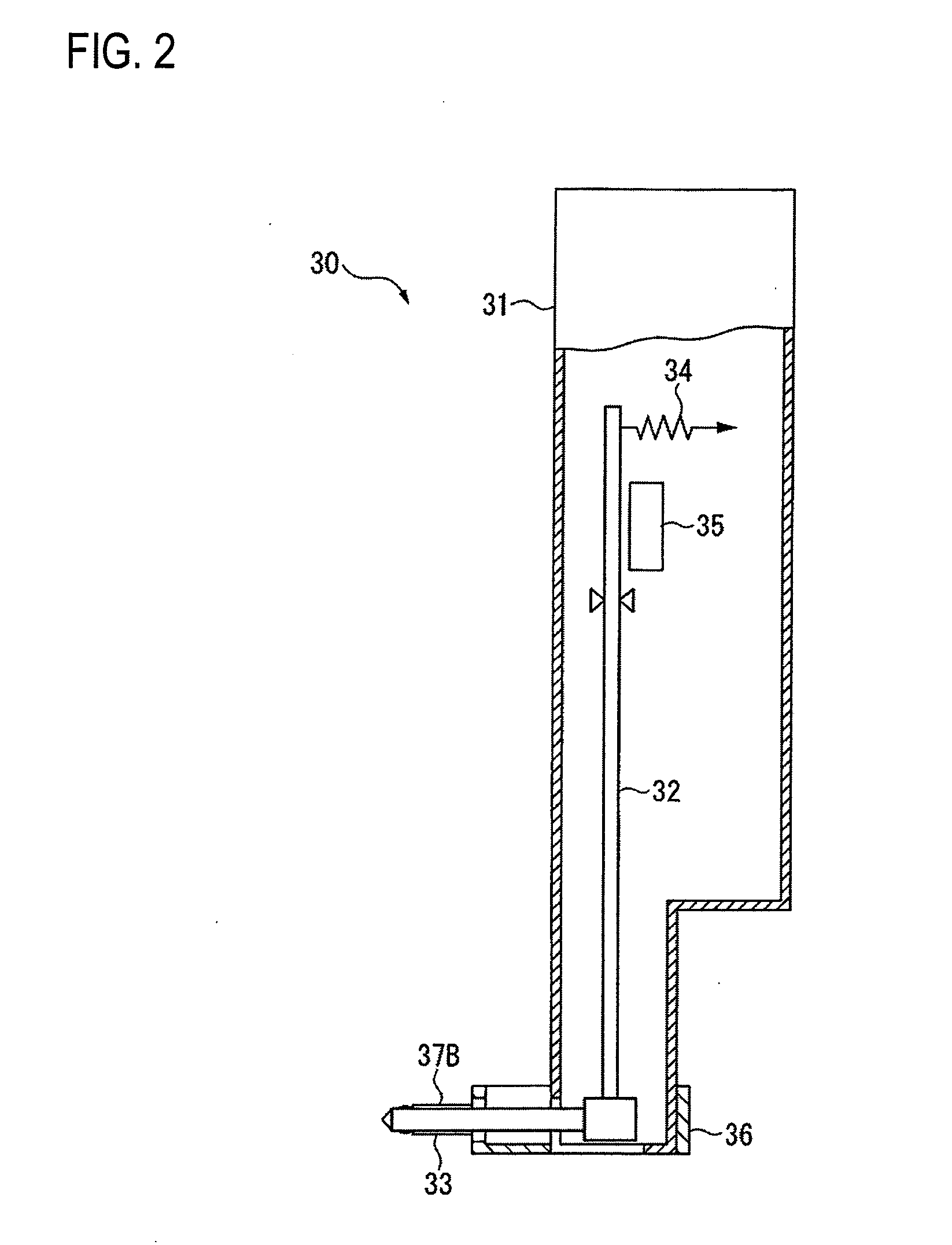
[0017]In the exemplary embodiment, the detector holder includes the guide member, the slide member holding the roughness detector, and an urging member for urging the slide member and thus the slide member is urged so that the skid always comes in contact with the measurement face of the measured substance. Therefore, if the measured substance is a measured substance with a large eccentricity amount, etc., of the measurement face, for example, even if it is a cam, follow-up operation of the slide member along the cam face is performed and continuous measurement can be conducted in a state in which the skid is always in contact with the cam face, so that the surface roughness of the cam face of the cam, etc., can be efficiently measured.
[0020]According to the exemplary embodiment, the skid includes a pair of skids sandwiching the stylus and projecting in the projection direction of the stylus. Thus, when the surface roughness is measured while the roughness detector is moved in the side-by-side direction of the stylus and the skids, one skid is always in contact with the measurement face in the proximity of the boundary of the measurement area, so that a measurement-impossible area can be prevented from occurring. Therefore, the measurement area can be enlarged without re-positioning the measured substance.
[0023]According to the invention, the tip of one skid deviates in the displacement direction of the stylus from the tip of the other skid, so that only one skid always comes in contact with the measurement face of the measured substance during measuring and thus the adverse effect on the measurement waveform can be prevented.

Problems solved by technology

However, in a case where the surface roughness of the cam face is measured using the roundness measuring device, the following problem occurs:

Method used


Image

  • Surface texture measuring device
  • Surface texture measuring device
  • Surface texture measuring device

Examples


modified examples

[0064]The invention is not limited to the embodiment described above and contains modifications, improvements, etc., in the range in which the object of the invention can be accomplished.

[0065]In the description of the embodiment, the surface roughness of the outer peripheral cam face of the plate cam (plane cam) is measured by way of example, but the embodiment can also be applied to measurement of the surface roughness of the end face cam face of an end face cam (solid cam), etc., as the measured substance W.

[0066]For example, as shown in FIG. 9, an end face cam (solid cam) as the measured substance W is set on the rotation table 20 (not shown) with the end face cam face of the end face cam (solid cam) upward and the roughness detector 30 is attached to the slide arm 44 so that the stylus 33 and the skids 37A and 37B become parallel with the vertical axis L. In this state, if the rotation table 20 is rotated, the surface roughness of the end face cam face of the end face cam (soli...


PUM


Abstract

A surface texture measuring device includes a rotation driving device configured to rotate a measured substance, a roughness detector including a stylus provided displaceably at a tip of a detector main body and at least one skid provided at the tip of the detector main body and in the proximity of the stylus and outputting displacement of the stylus based on the skid as an electric signal, and a detector driving device configured to drive a detector holder. The detector holder includes a guide member driven by the detector driving device, a slide member configured to hold the roughness detector and provided slidably in a displacement direction of the stylus to the guide member, and an urging member configured to urge the slide member so that the skid always comes in contact with the measurement face of the measured substance.

Description

TECHNICAL FIELD[0001]The present disclosure relates to a surface texture measuring device for measuring surface roughness of a measured substance. In particular, the present disclosure relates to a surface texture measuring device for measuring surface roughness of a measured substance with a large eccentricity amount and a large displacement amount on a measurement face, for example, the outer peripheral cam face of a plate cam (plane cam), the end face cam face of an end face cam (solid cam), etc.RELATED ART[0002]For example, to measure surface roughness of the outer peripheral cam face of a plate cam (plane cam), a roundness measuring device may be used for measurement.[0003]Generally, the roundness measuring device includes a base, a rotation table provided for rotation with a vertical axis as the center on the base for placing a measured substance on an upper face, a column provided upright on the base, a moving up and down slider that can move up and down in an up and down dir...

Claims


Application Information

Patent Timeline
IPC IPC(8): G01B5/28
CPCG01B5/28G01B5/201
Inventor YAMADA, KEIJIOTA, NORIMICHISHINDO, HIDEKI
Owner MITUTOYO CORP
Learn More