System to establish a refueling infrastructure for coming fuel-cell vehicles/marine craft and interim production of gaseous products, power, and inner-city rejuvenation

a fuel-cell vehicle/marine craft and infrastructure technology, applied in the field of composite facilities, can solve problems such as urban decay, firm closures, and spread of malady

Inactive Publication Date: 2011-06-16
DEDERICK ROBERT J
View PDF20 Cites 18 Cited by
  • Summary
  • Abstract
  • Description
  • Claims
  • Application Information

AI Technical Summary

Benefits of technology

In cases where a larger body of water capable of taking advantage of tidal flow is the adjacent water system, a compact floating energy generation system consisting of a barge mounted with various electrical energy producing devices is also contemplated. The barge equipment includes wind generators, wave generators and a hydro-electrical generator that is internal of the barge proper.

Problems solved by technology

When an industry, possibly the one which caused the city to grow up around it, closes its doors, urban decay begins.
Commercial firms near the industry go out of business due to the lack of traffic, and malady spreads.
The structures become eye-sores and attractive nuisances subject to vandalism and arson, not to mention the financial loss of tax revenue to the municipal coffers.
While the buildings may be structurally sound, no one wants them.

Method used


Image

  • System to establish a refueling infrastructure for coming fuel-cell vehicles/marine craft and interim production of gaseous products, power, and inner-city rejuvenation
  • System to establish a refueling infrastructure for coming fuel-cell vehicles/marine craft and interim production of gaseous products, power, and inner-city rejuvenation
  • System to establish a refueling infrastructure for coming fuel-cell vehicles/marine craft and interim production of gaseous products, power, and inner-city rejuvenation

Examples


second embodiment

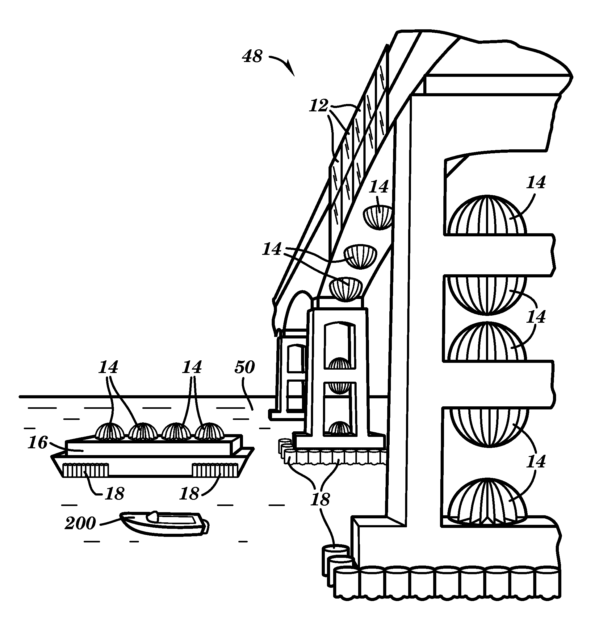
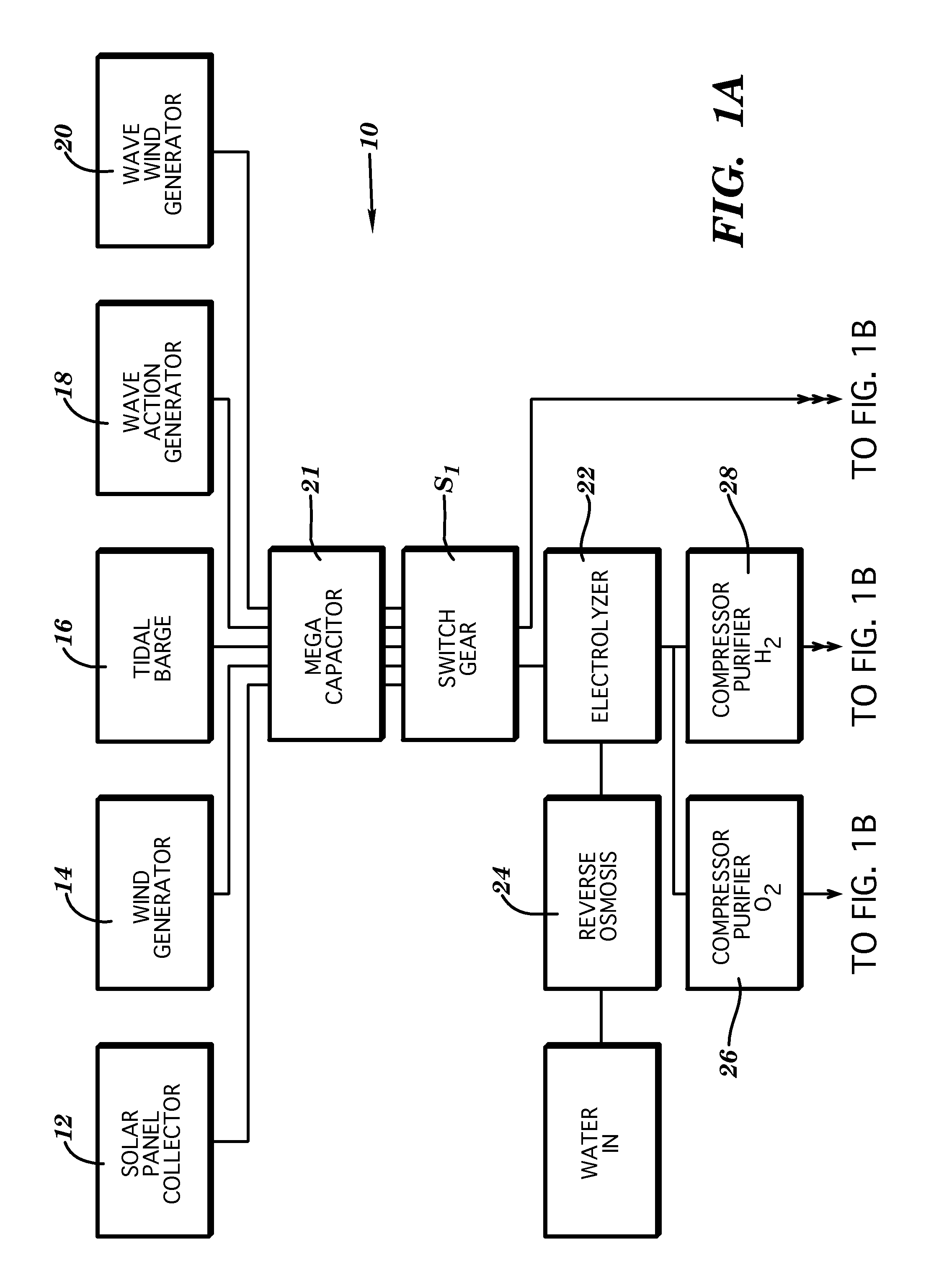
the system 10 is illustrated in FIG. 2B. As shown, a site 202 including buildings 204, 206, that had outlived their apparent usefulness, adjacent a waterway 208 possibly in an inner city environment are shown having a complex of solar panels 12 and vertical axis wind generators 14 operatively positioned thereon. A bridge 210 over the waterway 208 may be included at the site 202. A presently preferred site would be a textile mill that had a hydropower generating capability such that a turbine (not shown) may be housed therein in order to generate electrical power.

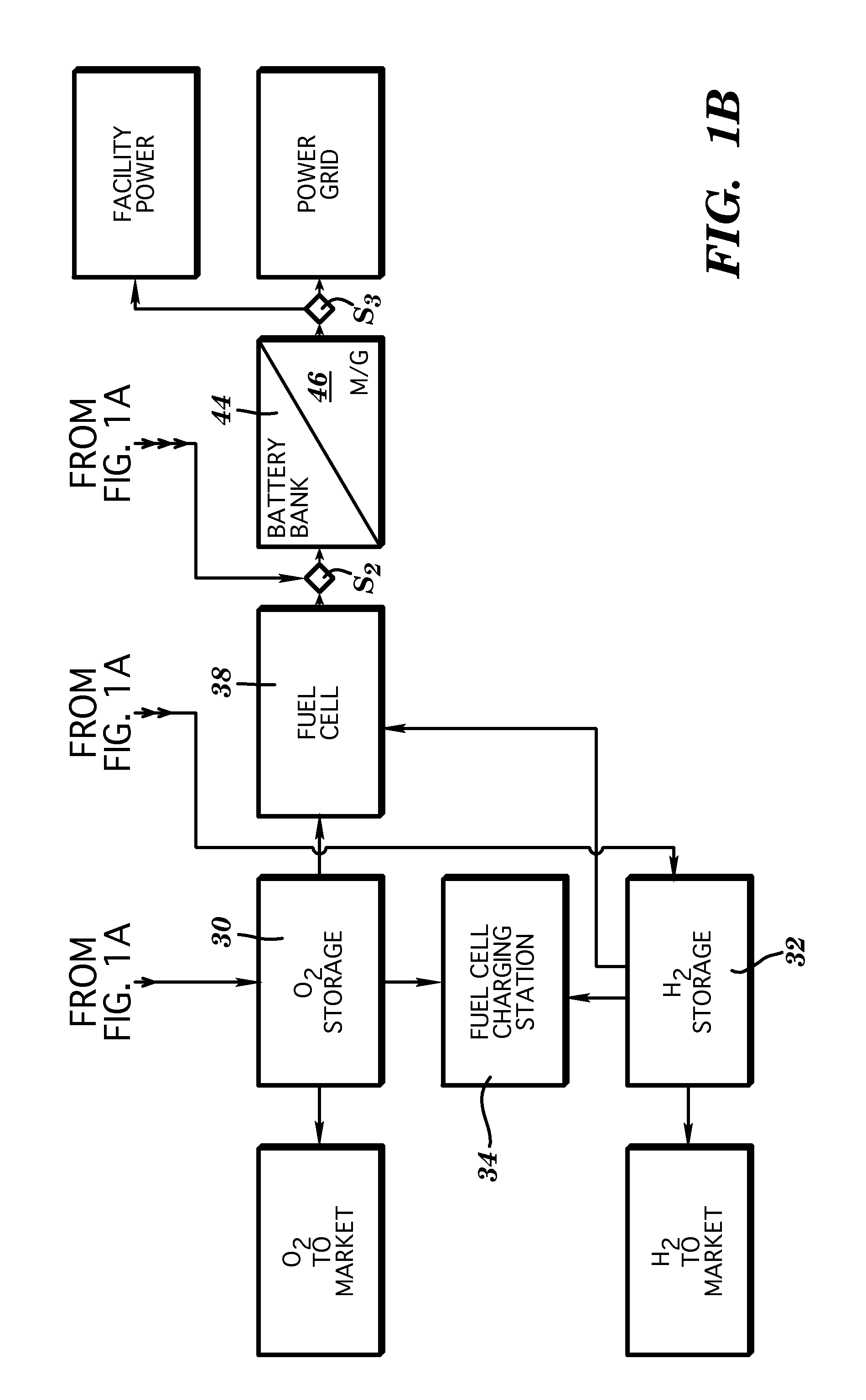
Also housed in the building is an electrolyzer (not shown) that breaks down the water into oxygen and hydrogen and may be stored in suitable tanks (not shown) inside or adjacent to the buildings 204, 206. The stored hydrogen and oxygen can either be sold or dispensed to fuel cell vehicles as well as used in a fuel cell to produce alternating current (AC) electricity which may be fed into the local power grid, provide AC curr...


PUM

PropertyMeasurementUnit
electricalaaaaaaaaaa
electrical conductionaaaaaaaaaa
alternating current poweraaaaaaaaaa

Abstract

A facility for the generation of electrical power and products for the refueling of vehicles including but not limited to, fuel cell vehicles (FCV's) and marine craft and for use by the facility and/or general market. A host of electrical power generation devices including solar panels, solar collectors, wave action generators, mega capacitors reverse osmosis water purification apparatus, high density capacitor electrolizers, hydrogen/oxygen purifiers and compressors, storage units, fuel cells, AC/DC motors and generators and the various connectors, gauges and networks used for interconnecting and dispensing the products of a combined source system are used jointly and severally in a land/marine readily available site. The idealized site for this combined system is a bridge or other elevated structure such as buildings. The siting structure is most desirably located adjacent a water source, be it a river, bay, tidal estuary or the like. In addition to the generation of DC electrical power, gaseous products such as oxygen and hydrogen may be marketed for their open market value or used in the production of additional power via fuel cell operation are also marketed or use/consumed on site. Unique improvements are made in wind generators, a tidal barge generation system and a wave air generator. Unique improvements are also made in the ability to store energy through use of capacitors.

Description

BACKGROUND OF THE DISCLOSURE1. Technical FieldThe instant disclosure relates, generally, to composite facilities that may be used to refuel non-polluting vehicles and marine craft. Specifically, the disclosure relates to a facility which generates and stores electrical power as hydrogen from a number of non-polluting, renewable sources, such as wind, water and solar sources. Most uniquely, the disclosure is situated in close proximity to and, in large part, on a generally man-made structure such as an industrial facility (possibly vacant), a bridge (possibly abandon), highway overpass system, or even an industrially polluted brown-field, in short, an area open to the sun and wind. Fullest potential of the disclosure is acquired when the facility is co-located adjacent a body of water, preferably moving.2. Related ArtThe following related art summaries are merely representative of portions of the disclosure disclosed in each reference. These summaries do not suffice for a thorough re...

Claims


Application Information

Patent Timeline
Patent Type & Authority Applications(United States)
IPC IPC(8): B65B3/04
CPCF03B13/142Y02E70/20F03B13/266F03B13/268F03B17/066F03D3/061F03D9/007F03D9/008F03D9/02F05B2220/61F05B2220/62F05B2220/708F05B2240/215F05B2240/216F05B2250/241Y02B10/30Y02B10/70Y02E10/28Y02E10/32Y02E10/38Y02E10/74Y02E70/10F03B13/148F03D9/19Y02B10/10Y02E10/30Y02E10/50Y02E60/36Y02E70/30Y02A20/141Y02A20/144F03D9/11F03D9/25F03D15/10H02S10/12Y02E10/20Y02E60/50
Inventor DEDERICK, ROBERT J.
Owner DEDERICK ROBERT J
Why Eureka
Try Eureka