

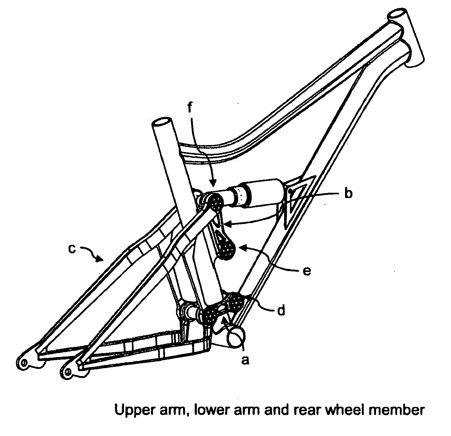
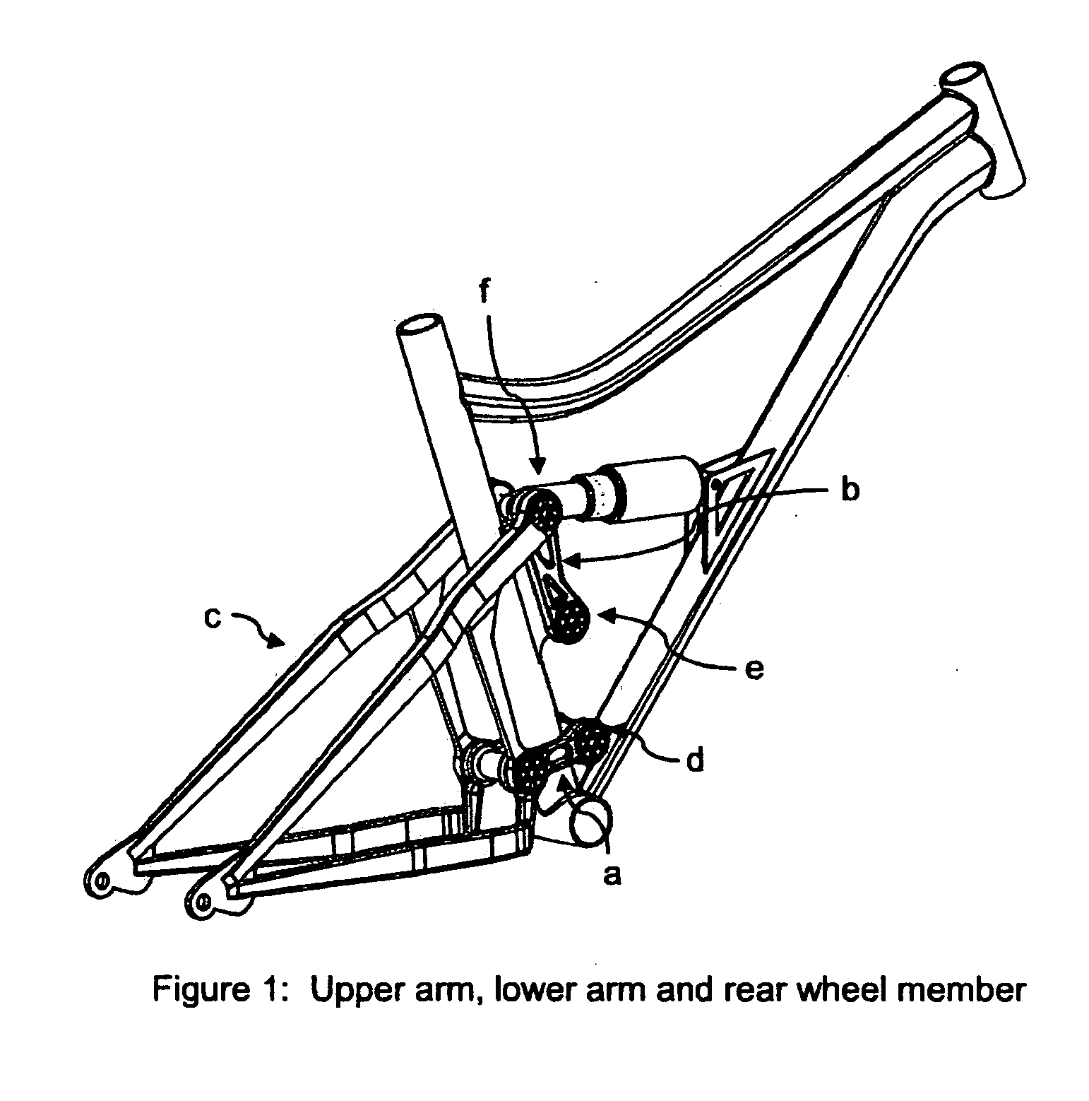
Suspension System for Chain-Driven or Belt-Driven Vehicles
a suspension system and chain drive technology, applied in the direction of suspension arms, resilient suspensions, motorcycles, etc., can solve the problems of difficult to maintain consistent anti-squat and anti-ris
- Summary
- Abstract
- Description
- Claims
- Application Information
AI Technical Summary
Benefits of technology
Problems solved by technology
Method used
Image

Examples
Embodiment Construction
1 Anti-Squat
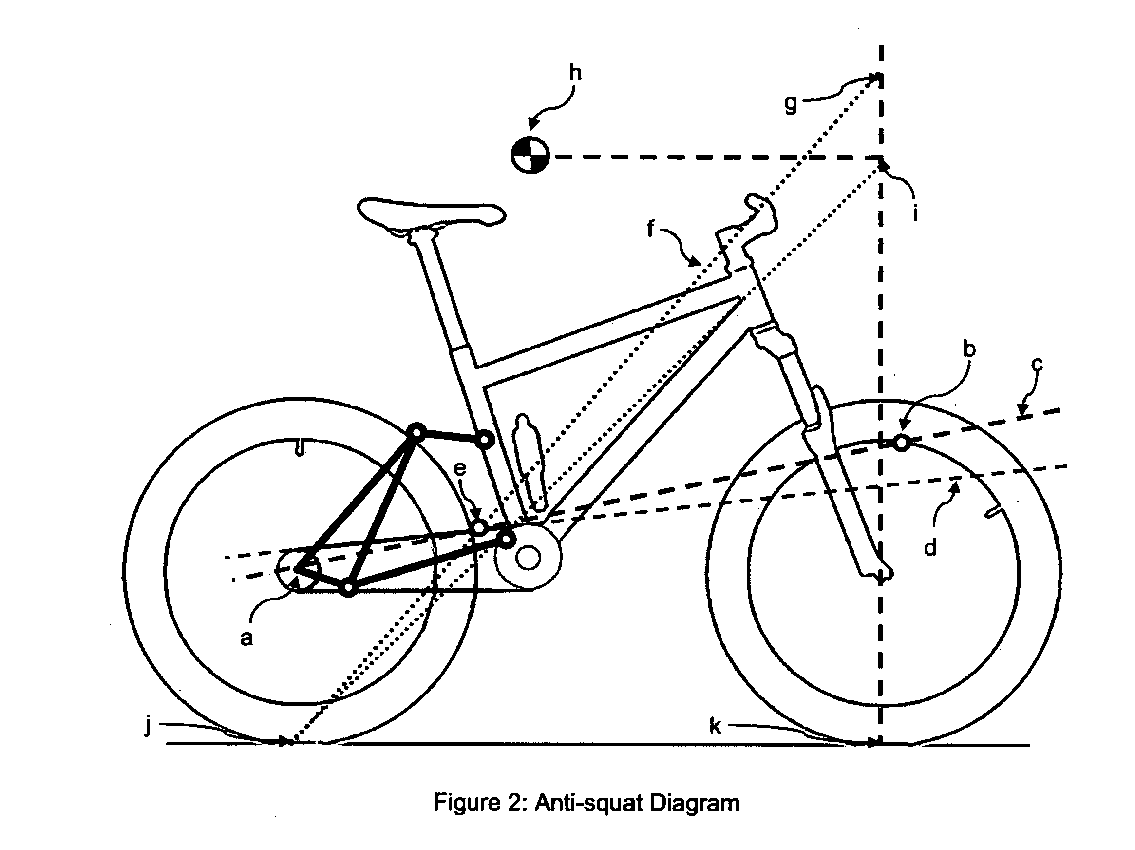
[0023]Anti-squat is described as a force that prevents the rear suspension from compressing due to weight transfer from acceleration. Bicycle suspensions have a natural tendency to compress or “squat” during acceleration. Having 100 percent anti-squat means that the suspension is able to totally counter the squatting force. The amount of anti-squat is calculated based on the diagram in FIG. 2.
[0024]Line 1 (2c) is defined by the rear axle (2a) and the current instantaneous center (2b). Line 2 is the chain force line (2d). The intersection of line 1 and line 2 defines point (2e). The line of anti-squat (2f) is defined by the rear tire contact patch (2j) and point (2e). The intersection of the anti-squat line and the vertical line from the front tire contact patch defines point (2g). The distance from point (2k) to point (2g) defines the amount of anti-squat. The percentage of anti-squat is measured from height (2i) which is at the same height as the center of gravity of th...
PUM
 Abstract
Description
Claims
Application Information