Planar transformer

a transformer and planar technology, applied in the direction of coils, printed circuit aspects, printed inductance incorporation, etc., can solve the problem of large construction height of transformers, and achieve the effect of low cost production

Inactive Publication Date: 2011-06-16
KROHNE MESSTECHNICK GMBH & CO KG
View PDF8 Cites 38 Cited by
  • Summary
  • Abstract
  • Description
  • Claims
  • Application Information

AI Technical Summary

Benefits of technology

[0013]Thus, it is a primary object of the invention to provide a planar transformer, which can be produced at a low cost and is compact, but is still suitable for the connection to intrinsically safe electronic circuits.

Problems solved by technology

Sections which are smaller than one third of the respective separation gap for this medium are seen as non-countable short circuit failures, insofar as the intrinsic safety is compromised.
Sections, which are greater than or equal to one third of the respective separation gap, are seen as countable short circuit failures, insofar as the intrinsic safety is thereby compromised.
The printed circuit boards required for this, having exceptionally large layer thicknesses, however, are excessively costly and result in large construction heights of the transformers.

Method used


Image

  • Planar transformer
  • Planar transformer
  • Planar transformer

Examples


Embodiment Construction

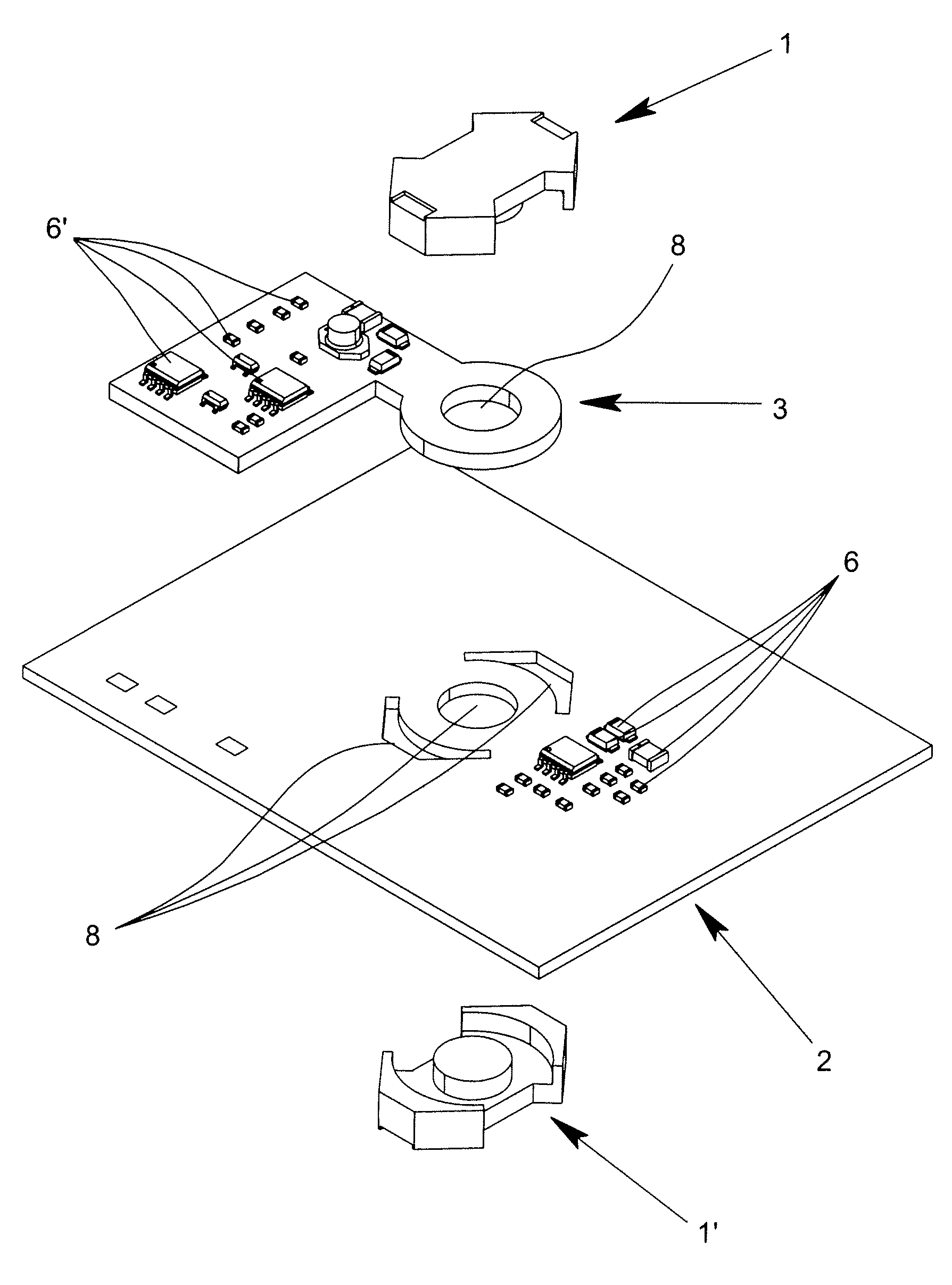
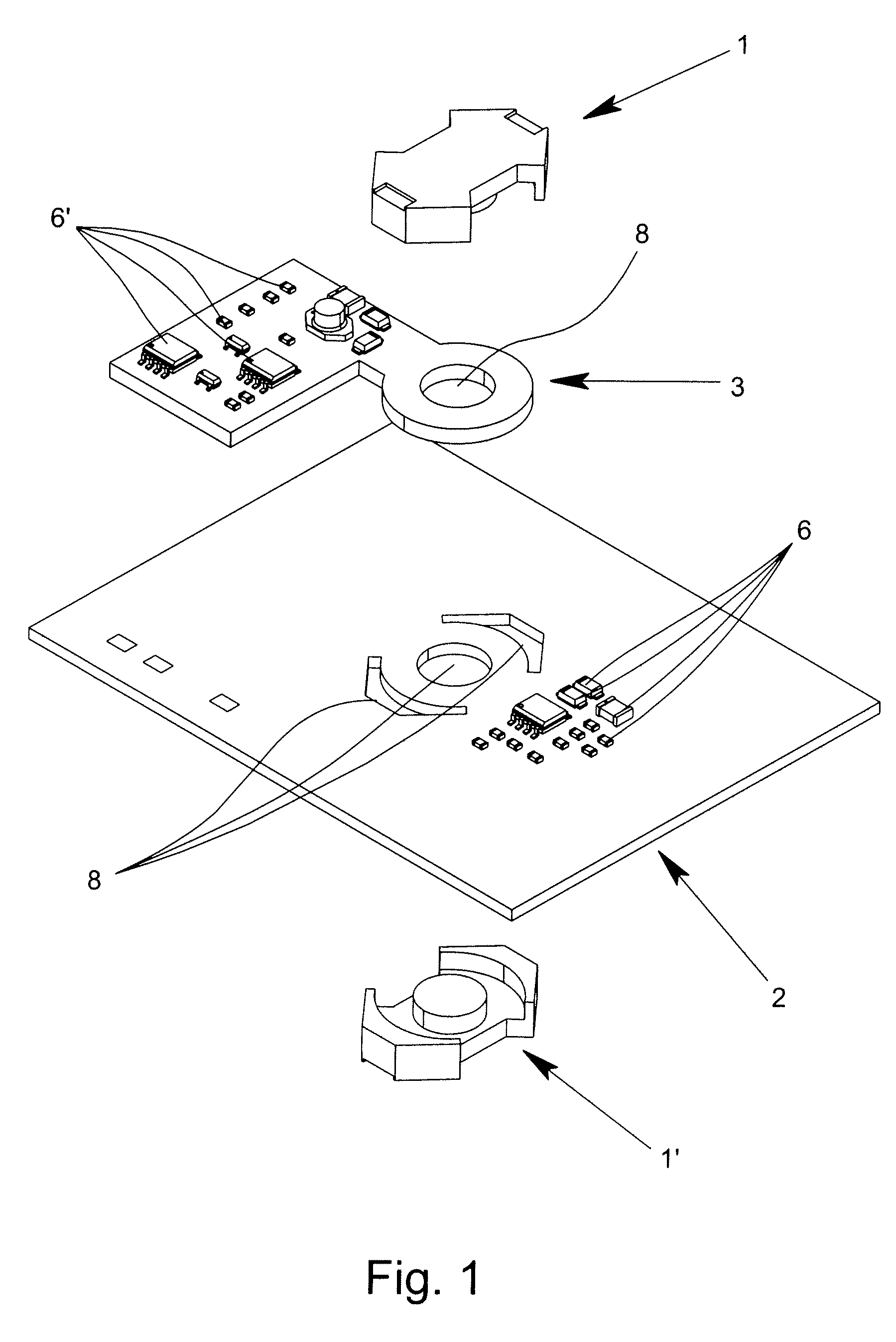
[0035]FIG. 1 shows a planar transformer according to the invention having a core 1, 1′, which is formed of two subcomponents, a first printed circuit board 2 and a second printed circuit board 3. As shown in FIGS. 2 & 3, a first winding 4 is arranged on the inside of the first printed circuit board 2 and a second winding 5 is arranged on the inside of the second printed circuit board. A plurality of components 6, 6′ is arranged on the first printed circuit board 2 and second printed circuit board 3. The first printed circuit board 2 has three openings 8 and the second printed circuit board 3 has one opening 8, through which the core 1, 1′ formed of two E-shaped half-shells extends.

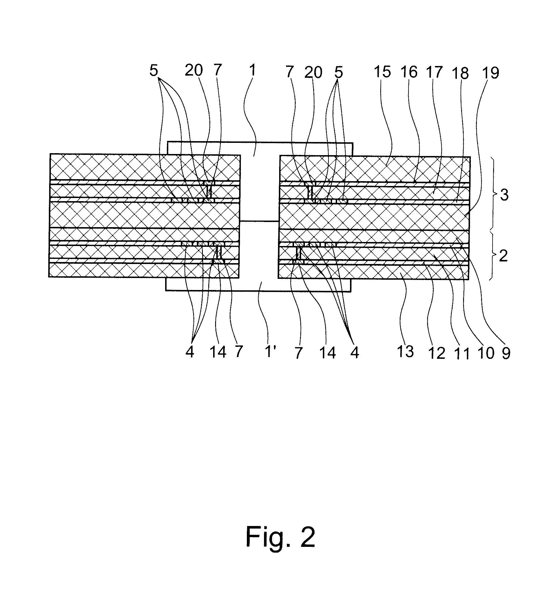
[0036]FIG. 2 schematically shows the first printed circuit board 2 and the second printed circuit board 3 in the area of the core 1, 1′. The first printed circuit board 2, as well as the second printed circuit board 3, are multi-layer printed circuit boards. The first printed circuit board 2 is, here, a st...


PUM

PropertyMeasurementUnit
conductiveaaaaaaaaaa
electric energyaaaaaaaaaa
creepage distancesaaaaaaaaaa

Abstract

A planar transformer suitable for intrinsically safe electronic circuits with a core, a first printed circuit board and a second printed circuit board. The first printed circuit board has a first winding and the second printed circuit board has a second winding. The planar transformer can be produced at a low cost and is compact, but is still suitable for connection to intrinsically safe operating circuits is implemented by at least one gap being asymmetrically split on the first printed circuit board and the second printed circuit board.

Description

BACKGROUND OF THE INVENTION[0001]1. Field of Invention[0002]The invention relates to a planar transformer with a core, a first printed circuit board and a second printed circuit board, wherein the first printed circuit board has a first winding and the second printed circuit board has a second winding and the planar transformer is suitable for intrinsically safe electronic circuits.[0003]2. Description of Related Art[0004]Regulations for the construction and testing of intrinsically safe operating means, which are intended for use in areas in danger of gas explosions, as well as for related operating means, which are intended for the connection to intrinsically safe electronic circuits that lead into such areas, are specified by the standard EN 60079-11. This standard is also valid for electric operating means or parts of electric operating means, which are found outside of the area in danger of gas explosions or are protected by another type of ignition protection according to IEC ...

Claims


Application Information

Patent Timeline
Patent Type & Authority Applications(United States)
IPC IPC(8): H01F5/00
CPCH01F27/2804H01F2027/2809H05K2201/086H05K1/141H05K1/165H05K1/0256
Inventor HERHOLD, WOLFGANG
Owner KROHNE MESSTECHNICK GMBH & CO KG
Why Eureka
Try Eureka