
Use of one LED to represent various utility rates and system status by varying frequency and/or duty cycle of LED

a technology of led and utility rate, applied in the field of modules, can solve the problems of increasing the complexity and cost of an individual home appliance and the demand supply management system, and the corresponding cost of using the utility, and achieve the effects of reducing the cost of the simplified form of communication, low cost and small siz

Active Publication Date: 2011-06-16
HAIER US APPLIANCE SOLUTIONS INC
View PDF9 Cites 20 Cited by
  • Summary
  • Abstract
  • Description
  • Claims
  • Application Information

AI Technical Summary

Benefits of technology

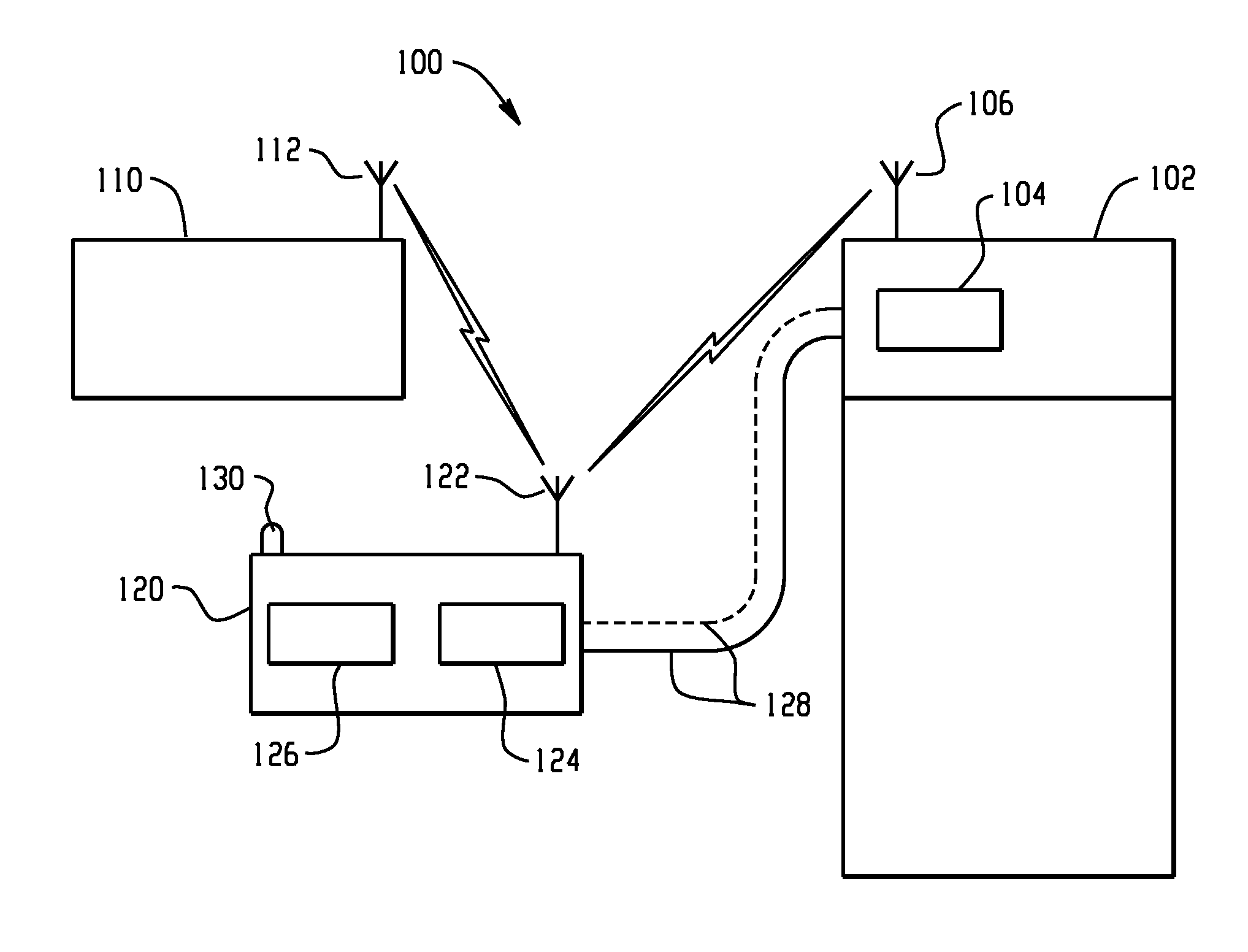
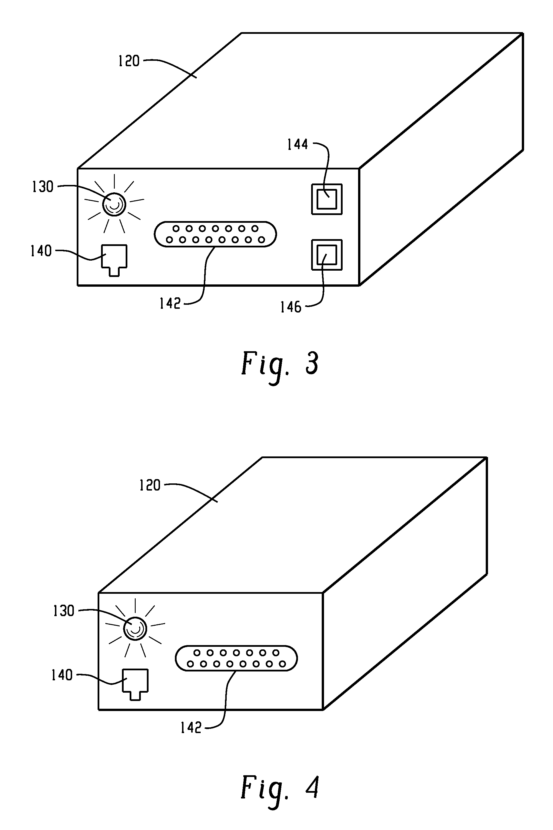
The patent describes a system and method for displaying information about the cost of energy use and signal strength of an appliance. This is done through a low power indicator, such as a single LED device, that is associated with the appliance. The LED device can be actuated in response to different data received from a module, and can display information in a variety of ways, such as a steady illuminated state, a slow FLASH state, or a fast FLASH state. The LED device can be mounted on the external surface of the appliance or module. The system is simple, small, low cost, and low power consumption, with no loss of functionality. The technical effects of the patent include the ability to display real-time information about energy use and signal strength, and to provide a convenient and low-cost means of communication for the associated appliance.

Problems solved by technology

When demand is high, a corresponding cost of using the utility is high and a user is apprised of the increased utility rate.
Although such a complex user interface associated with each home appliance may be informative, it adds to the complexity and cost of an individual home appliance and the demand supply management system.
Still another problem is how to conserve energy associated with the module, individual home appliance, or demand supply management system.

Method used


Image

  • Use of one LED to represent various utility rates and system status by varying frequency and/or duty cycle of LED
  • Use of one LED to represent various utility rates and system status by varying frequency and/or duty cycle of LED
  • Use of one LED to represent various utility rates and system status by varying frequency and/or duty cycle of LED

Examples


Embodiment Construction

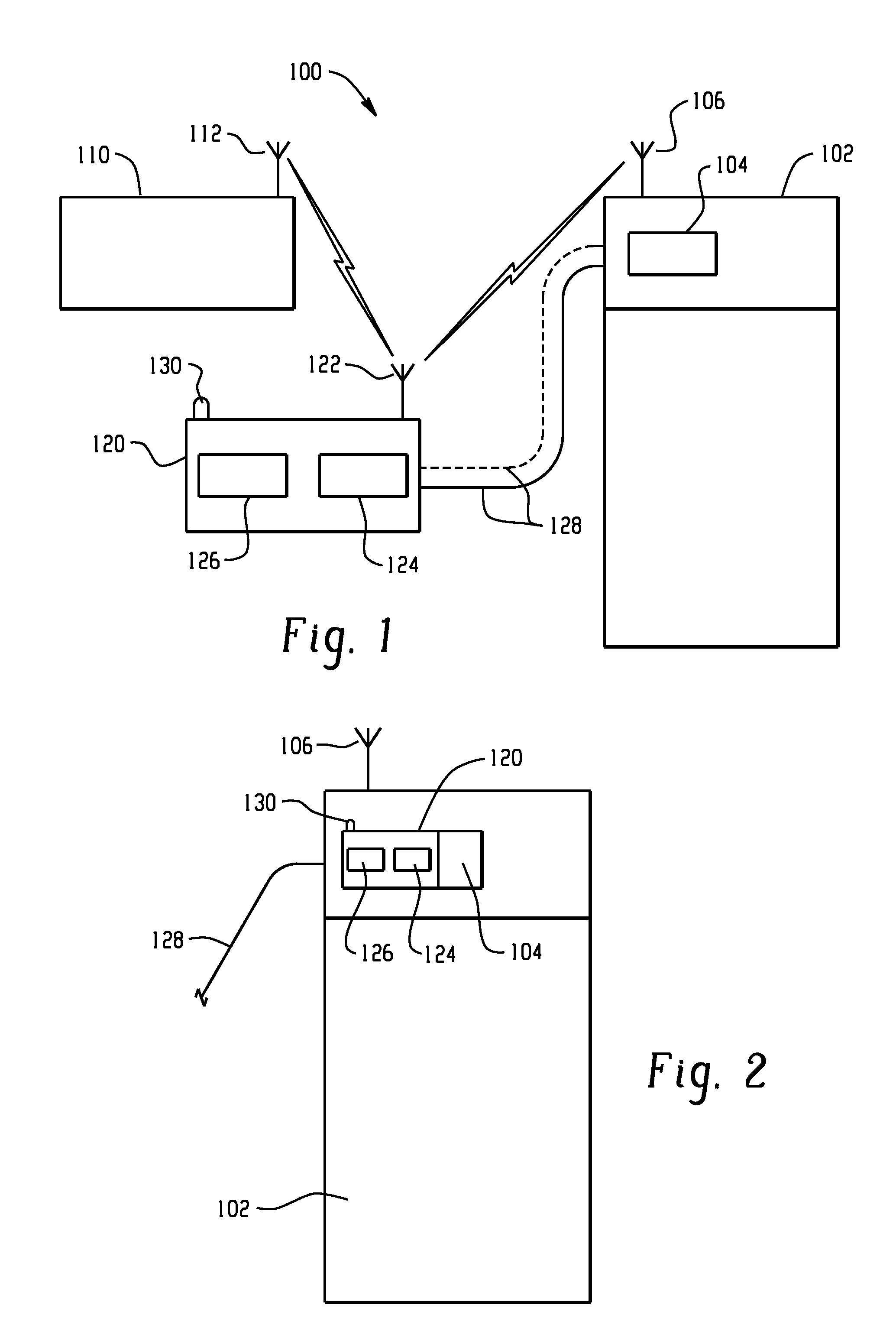
[0027]Turning first to FIG. 1, a first embodiment of a demand / response or demand / supply management system 100 is schematically illustrated. The system 100 includes one or more home appliances 102, each of which includes an associated microprocessor, microcontroller, or controller 104. The controller 104 controls operational aspects of the home appliance. Without unduly limiting the present disclosure, one example of a home appliance 102 is a refrigerator having a controller 104 that controls a temperature of the refrigerator compartment and / or associated freezer compartment. In a demand supply management system, the temperature may be altered in response to the cost of energy. For example, if a particularly high demand is experienced or imposed on the utility, the cost of that utility will likewise increase. A data transmitter 110 may be associated with a utility (electricity, gas, water, etc.) which emits data, for example wirelessly through antenna 112 or alternatively through a h...


PUM


Abstract

A demand supply management system for an appliance receives information related to cost of energy use and communicates data to the associated appliance in response thereto. A single chip, light emitting diode (LED) device is preferably associated with a module or portion of the home appliance. The LED device conveys information relating to at least two of cost of energy use, signal strength, and module status. The LED device is preferably a single chip, single color solid-state LED device that is selectively actuated between “illuminated” and “non-illuminated” states, steady on, slow flash, fast flash, varying duration, intermittent “illuminated” and “non-illuminated”, etc. to convey information to the user.

Description

BACKGROUND OF THE DISCLOSURE[0001]The present disclosure relates to a module connected to a home appliance that provides a simple structure and manner of indicating at least two items of information, for example, at least two of network status, signal strength, and / or energy rate / level. More particularly, the disclosure relates to a low power indicator, preferably a single chip light emitting diode or LED device, that switches between the different items of information or modes, one of the modes being a default mode.[0002]A recent development in the area of home appliances is to provide appliances that respond to demand supply management (DSM) signals from utilities for example to affect a possible load shedding event in the appliances. One approach is to employ a module operatively connected to the appliance that receives the signal from a utility, home energy manager, or other source that indicates a demand for the particular utility (electricity, gas, water, etc.). When demand is...

Claims


Application Information

Patent Timeline
Patent Type & Authority Applications(United States)
IPC IPC(8): G09F9/33
CPCH02J2003/143H02J3/14H02J2310/14
Inventor KOBRAEI, HENRYBESORE, JOHN K.FINCH, MICHAEL F.DRAKE, JEFF DONALD
Owner HAIER US APPLIANCE SOLUTIONS INC
Learn More