Photochromatic coating for controlling lens flare

a technology of photochromatic coating and lens flare, which is applied in the field of photochromatic coating for controlling lens flare, can solve the problems of lens flare, housing may not be large enough to include a component extending beyond the periphery of the lens, and the control of lens flare in the electronic device camera is well-known. , to achieve the effect of reducing lens flar

Inactive Publication Date: 2011-06-16
APPLE INC
View PDF23 Cites 36 Cited by
  • Summary
  • Abstract
  • Description
  • Claims
  • Application Information

AI Technical Summary

Benefits of technology

[0005]This is directed to coating a lens of an electronic device with at least one photochromatic coating to reduce lens flare in images capture

Problems solved by technology

Controlling lens flare in an electronic device camera is a well-known problem.
As devices get smaller, however, the housing may not be sufficiently large to include a component extend

Method used


Image

  • Photochromatic coating for controlling lens flare
  • Photochromatic coating for controlling lens flare
  • Photochromatic coating for controlling lens flare

Examples


Embodiment Construction

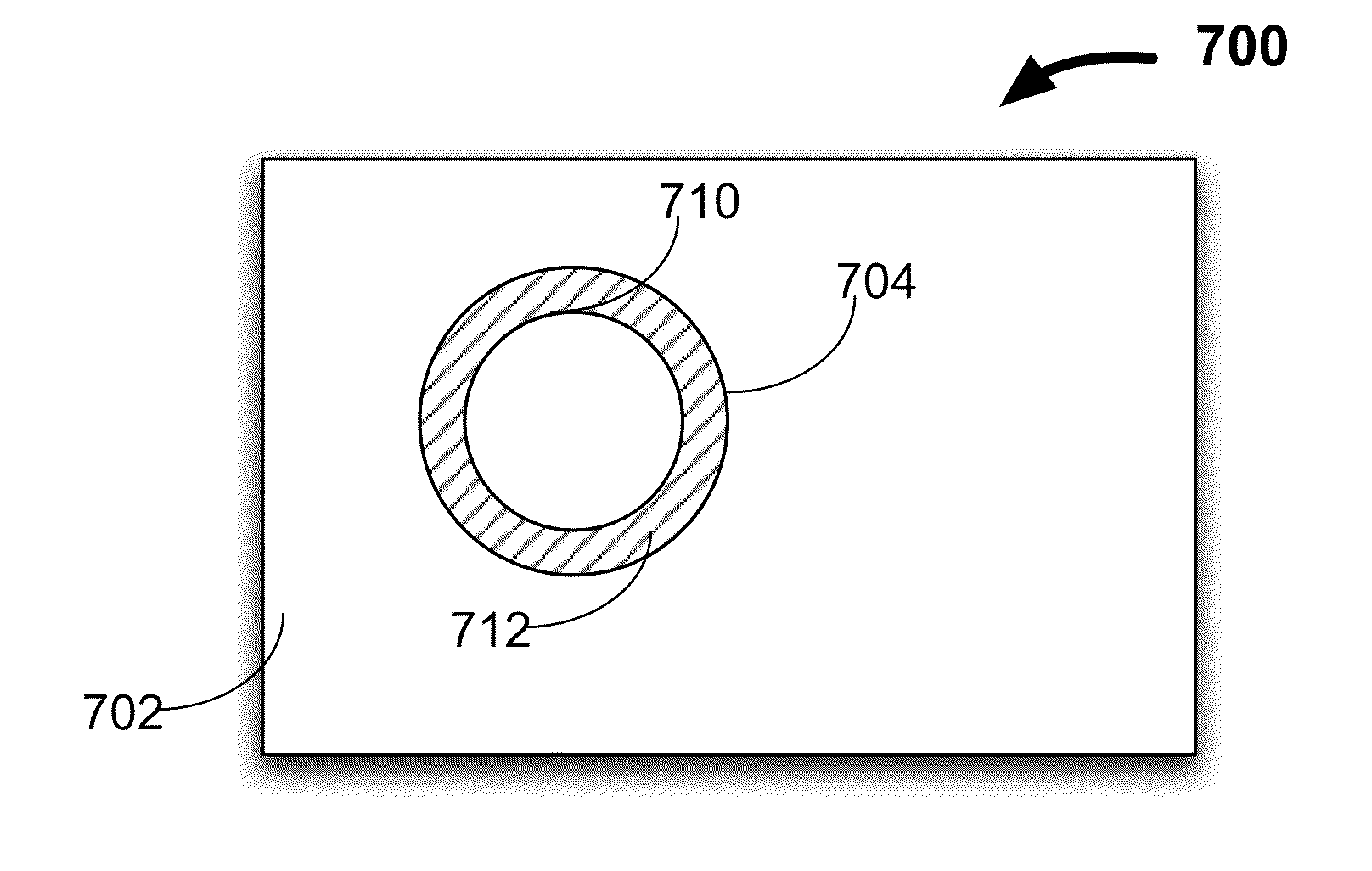
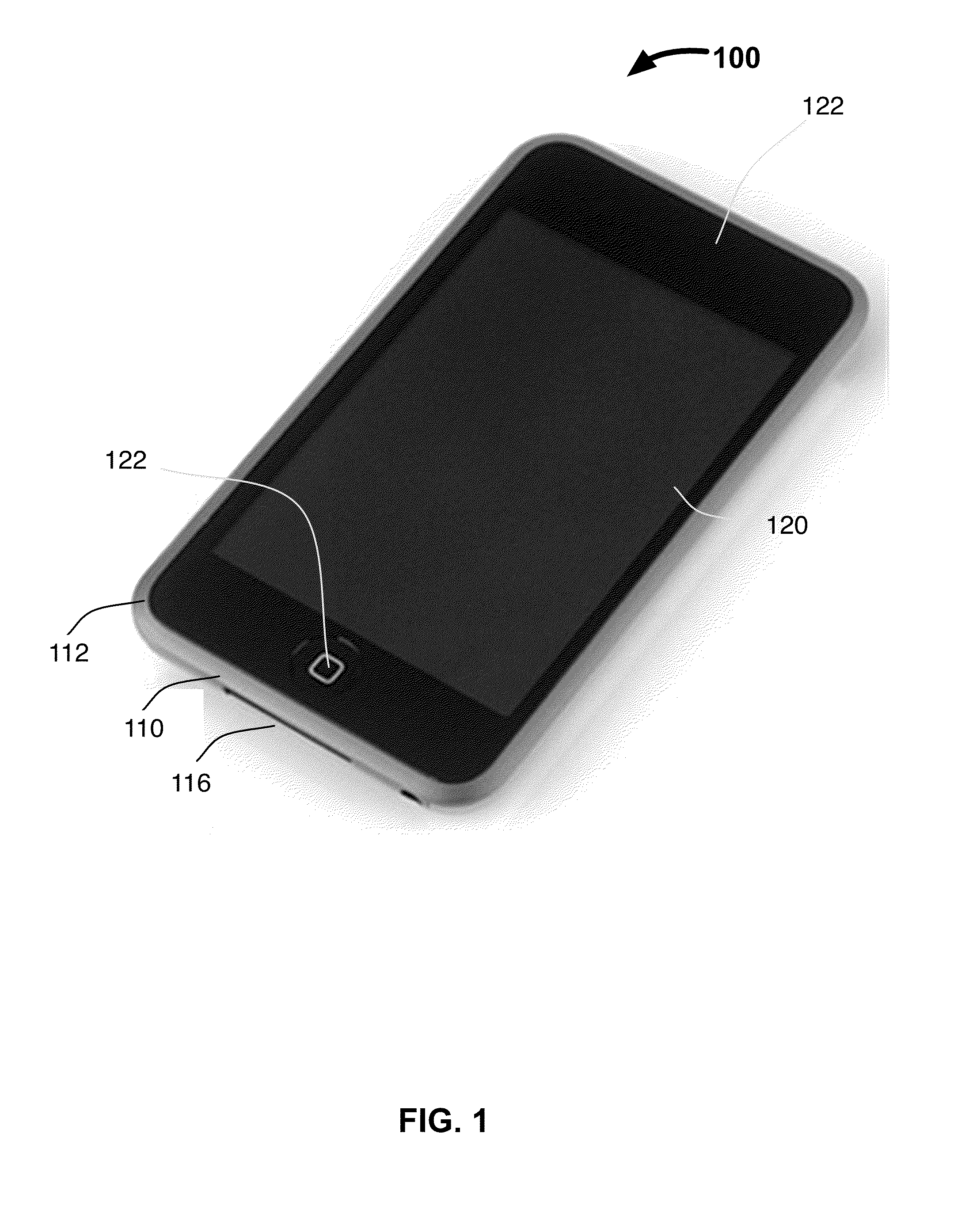
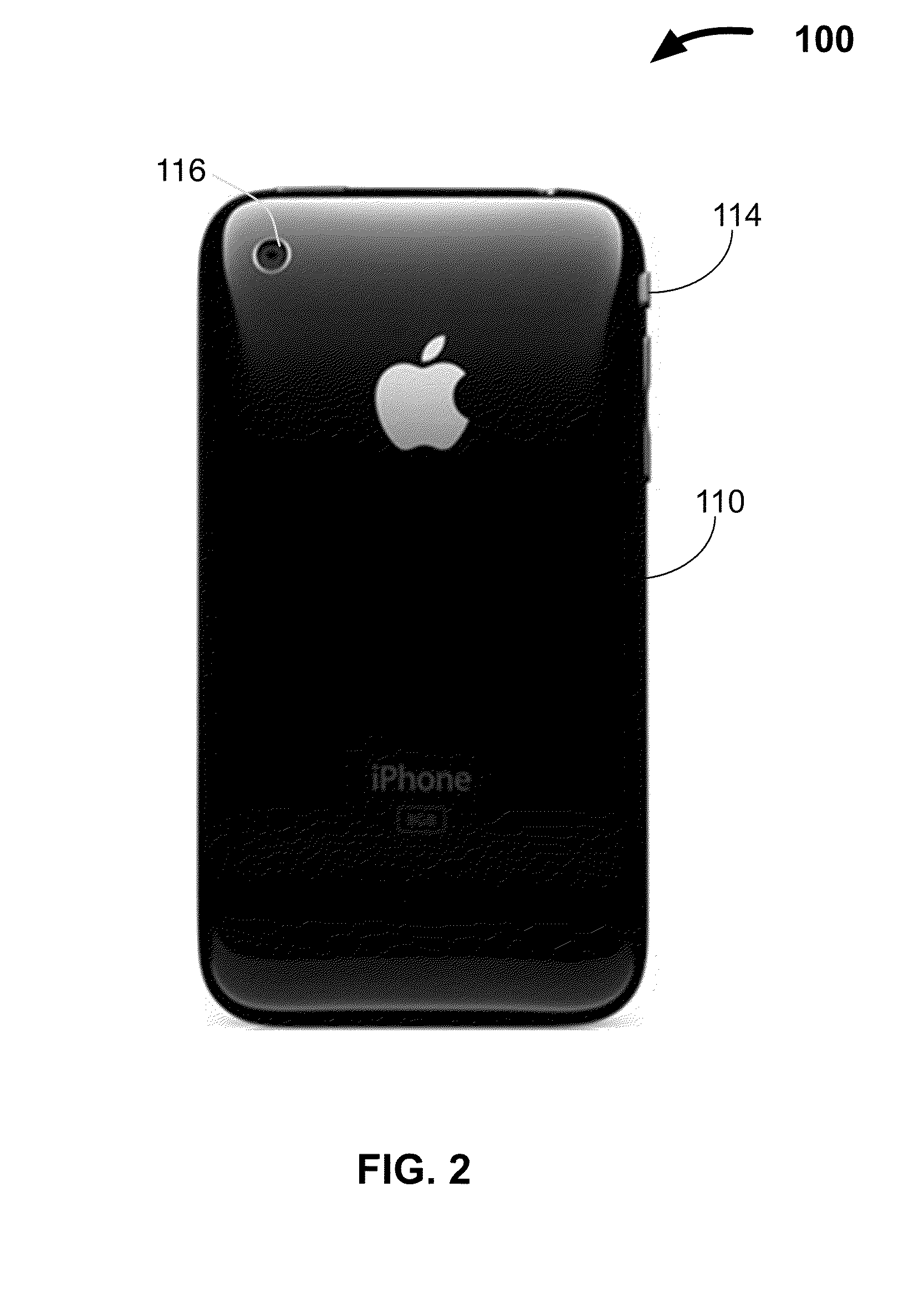
[0023]An electronic device can include a camera for capturing images of the user's environment. The camera can include a lens placed along the device housing, and a sensor positioned behind the lens such that light can be gathered by the lens and provided to the sensor. To ensure that images captured by the camera do not include lens flare, the lens can be stepped back relative to the housing. This can prevent stray light that is not within the field of view of the sensor from reaching the sensor.

[0024]As electronic devices become smaller, however, the electronic device may become too small for the lens to be recessed, or for a component (e.g., a hood) to extend from the device housing). The resulting electronic device may then have no or limited protection from lens flare, which can adversely affect the quality of images captured by the camera. As an alternative to a recessed lens or a housing extension, a photochromatic treatment or coating can instead be applied to at least one p...


PUM


Abstract

A camera lens can be subject to lens flare due to light reaching a camera sensor from outside of the camera field of view. When an electronic device size is reduced such that a lens cannot be recessed relative to the device housing, the lens can capture stray light. To reduce the chance that stray light reaches the lens and sensor, the lens can be treated with a photochromatic treatment. Properties of the photochromatic treatment, as well as the distribution of the treatment can be selected to reduce lens flare caused by particular types of light. In some embodiments, a photochromatic treatment can instead or in addition be applied for a cosmetic purpose. For example, a photochromatic treatment can be applied to a device housing, icons or text displayed on the device enclosure, on a mask within a device display window, or any other electronic device enclosure component.

Description

BACKGROUND OF THE INVENTION[0001]This is directed to using a photochromatic coating on plastic or glass used as part of a camera assembly to control lens flare.[0002]The exterior of many electronic devices can include a housing combined with a display area. The housing can include one or more openings through which a sensor or input interface can be accessed. For example, the housing can include one or more openings through which a button can be accessed. As another example, the housing can include one or more openings for a connector interface used to connect the device to a host device or to a power supply. As still another example, the housing can include an opening through which a sensor can receive or detect information from the user's environment. In one implementation, the housing can include an opening for a camera operative to detect light reflected from the user's environment.[0003]To capture an image, a camera sensor of the electronic device can receive light from the env...

Claims


Application Information

Patent Timeline
IPC IPC(8): H04N5/225G02B5/23
CPCG02B5/005G02B27/0018G02B5/23
Inventor MITTLEMAN, ADAM
Owner APPLE INC
Why Eureka
Try Eureka