Image projection device

a projection device and image technology, applied in the field of image projection devices, can solve the problems of long holding the device in the hand, void (vignetting) of the projected image, defect (trapezoidal distortion), etc., and achieve the effects of high image quality, high image quality, and high light flux scanning speed

Inactive Publication Date: 2011-06-16
KONICA MINOLTA OPTO
View PDF7 Cites 38 Cited by
  • Summary
  • Abstract
  • Description
  • Claims
  • Application Information

AI Technical Summary

Benefits of technology

[0026]In the image projection device according to any one of the first to twelfth aspects, the rotation of the reflection part around the two axes is controlled under the conditions that the image distortion along one scanning direction is visually observed. Thereby, the image distortion along the one scanning direction is corrected, and the scanning speed of the light flux along the other scanning direction is kept substantially constant. This enables an image having a high image quality to be projected even in a small-size image projection device.
[0027]In the image projection device according to any one of the second to eighth aspects, even when the light flux is projected with a certain degree of large inclination relative to the projection surface, the image distortion exceeding 20 percent along the one scanning direction is corrected by the control of the rotation of the reflection part and the projection optical system, and the image distortion along the other scanning direction is corrected by the projection optical system. This enables an image having a high image quality to be projected even in a small-size image projection device.

Problems solved by technology

However, holding the device in a hand for a long time is not preferable because it causes fatigue.
In such a case, however, if the projection is performed simply toward the front side, a part of a projected image is projected onto the desk or the floor, thus causing a void (vignetting) of the projected image.
However, in a case of a deflection / scanning device having no optical system (projection optical system) which projects a deflected light to a projection surface, a defect (trapezoidal distortion) is caused in which an image (projected image) on the projection surface is distorted into a trapezoidal shape.
Along with the distortion, non-uniformity of a scanning angle occurs between an upper portion and a lower portion of the screen, and thus non-uniformity of the resolution on the screen also occurs.
Therefore, a high-quality image cannot be projected.

Method used


Image

  • Image projection device
  • Image projection device
  • Image projection device

Examples


first embodiment

Outline Configuration of Image Projection Device

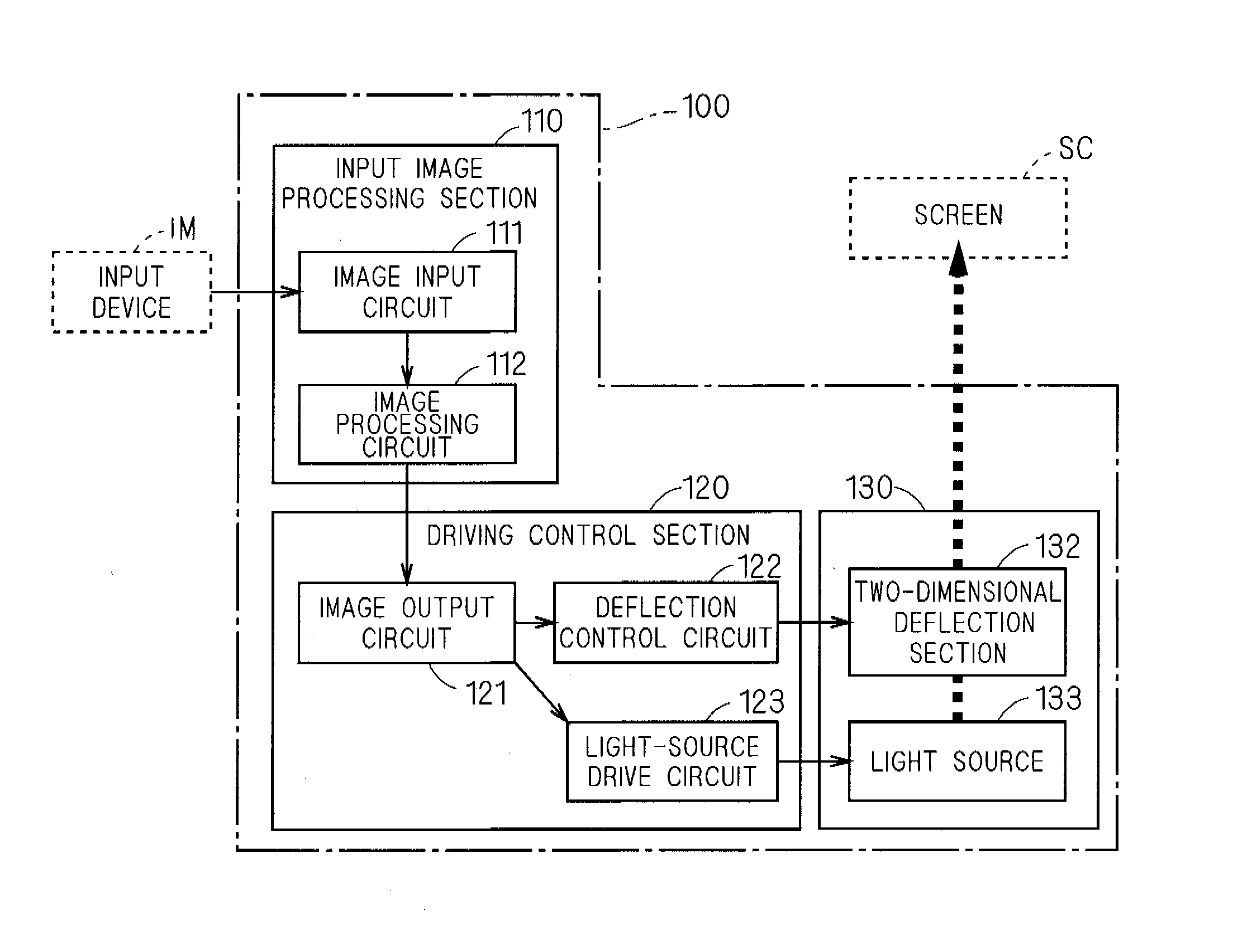
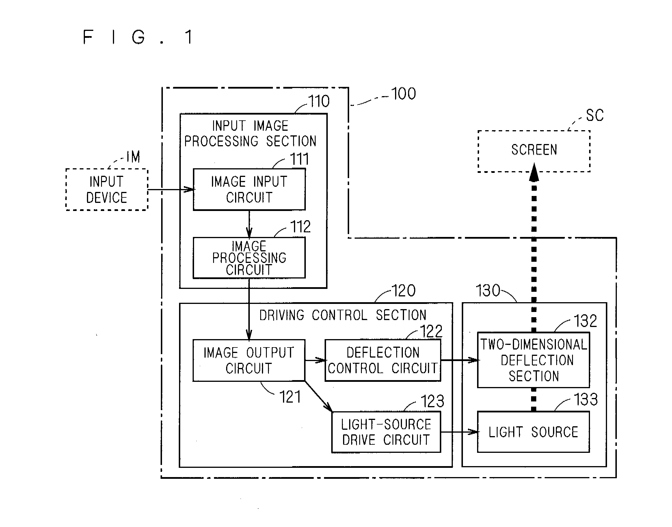
[0084]FIG. 1 is a block diagram showing a function configuration of the image projection device 100 according to a first embodiment of the present invention. The image projection device 100 is a device which projects a moving image to the screen SC which is the projection surface, and mainly includes an input image processing section 110, a driving control section 120, and an optical mechanism section 130.

[0085]The input image processing section 110 includes an image input circuit 111 and an image processing circuit 112.

[0086]The image input circuit 111 receives an image signal inputted from an input device IM, and outputs it to the image processing circuit 112. The image processing circuit 112 appropriately performs image processing on the image signal from the image input circuit 111, and outputs it to the driving control section 120.

[0087]Here, examples of the input device IM include a personal computer (PC), and examples of the ima...

second embodiment

[0222]In the image projection device 100 according to the first embodiment, the deflection / scanning driving correction is performed with respect to the uniform speed in the vertical scanning direction and the distortion in the horizontal scanning direction. On the other hand, in an image projection device 100A according to a second embodiment, assuming the application under the conditions that the projection angle θ is about 20° or more, the horizontal scanning distortion is corrected by a combination of the deflection / scanning driving correction and a correction (hereinafter also referred to as an “optical correction”) using a projection optical system, and the vertical scanning distortion is also corrected by the optical correction. Hereinafter, the image projection device 100A according to the second embodiment will be described. The image projection device 100A according to the second embodiment has configurations similar to that of the image projection device 100 according to t...


PUM


Abstract

An object is to provide a image projection device which has a small size but can project an image having a high image quality. To achieve the object, in an image projection device, a reflection part which reflects a light flux from a light source is, while being rotated around a first axis by non-resonance driving, rotated by resonance driving around a second axis which is substantially perpendicular to the first axis, and thereby the light flux is deflected in a two-dimensional direction. By controlling the rotation of the reflection part, a correction for suppressing an image distortion along one scanning direction on a projection surface, and a correction for keeping substantially constant a scanning speed of the light flux along the other scanning direction on the projection surface, are performed. Here, the relationship of 10°<θ<70° is satisfied, where θ represents an angle of inclination of the light flux, which is projected to the projection surface, toward the other scanning direction relative to a normal line of the projection surface, in a case where the reflection part is in a central position of the rotations around the first and second axes.

Description

RELATED APPLICATIONS[0001]This application is a U.S. National Stage Application under 35 U.S.C. 371 of International Application No. PCT / JP2009 / 062777, filed with Japanese Patent Office on Jul. 15, 2009, which claims priority to Japanese Patent Application No. 2008-209883, filed Aug. 18, 2008.TECHNICAL FIELD[0002]The present invention relates to an image projection device which projects an image to a projection surface. In more detail, the present invention relates to a small-size image projection device which two-dimensionally deflects and scans a light to project an image, and particularly to an optical system thereof. In further detail, the present invention relates to a small-size, so-called optical engine part of a pocket projector, a data projector, a rear-projection TV, or the like.BACKGROUND ART[0003]Various small-size image projection devices have been proposed which two-dimensionally deflect and scan a light from a light source and project an image (for example, Patent Doc...

Claims


Application Information

Patent Timeline
Patent Type & Authority Applications(United States)
IPC IPC(8): G03B21/28
CPCG02B26/0841H04N9/3129G03B21/00G02B26/101G03B21/005
Inventor KONNO, KENJIMIZUMOTO, KENJI
Owner KONICA MINOLTA OPTO
Why Eureka
Try Eureka