Supercharge Your Innovation With Domain-Expert AI Agents!

Vehicle lamp

a technology for vehicles and lamps, applied in the field of vehicles, can solve the problems of erroneous combining of structures and the inability to match the erroneous assembly prevention members of these components to each other,

Inactive Publication Date: 2011-06-16
STANLEY ELECTRIC CO LTD
View PDF9 Cites 0 Cited by
  • Summary
  • Abstract
  • Description
  • Claims
  • Application Information

AI Technical Summary

Benefits of technology

The present invention relates to a vehicle headlamp that prevents incorrect assembly due to different specifications. The headlamp includes a light source, a first reflector and a second reflector, a convex lens, and a shade. The one component and the other component can be assembled to be brought into contact with each other at corresponding contact areas. The one component and the other component can have corresponding erroneous-assembly prevention members at the corresponding contact areas to prevent mating with different components according to different specifications. The plurality of specifications can include a first specification and a second specification, and the erroneous-assembly prevention members can include a projection and a concave portion for receiving the projection. This prevents the incorrect assembly of components and ensures the proper functioning of the vehicle headlamp.

Problems solved by technology

In this case, because of the existence of the two types of the second reflectors and the two types of the shades, these structures may be erroneously combined during assembly and delivered to a user without correcting this fault.
In this case, when a first unit including the shade according to a particular specification is attempted to be assembled to a second unit including a second reflector according to a different specification, the erroneous-assemble prevention members of these components cannot be matched to each other because of different positional relationships.

Method used


Image

  • Vehicle lamp
  • Vehicle lamp
  • Vehicle lamp

Examples


Embodiment Construction

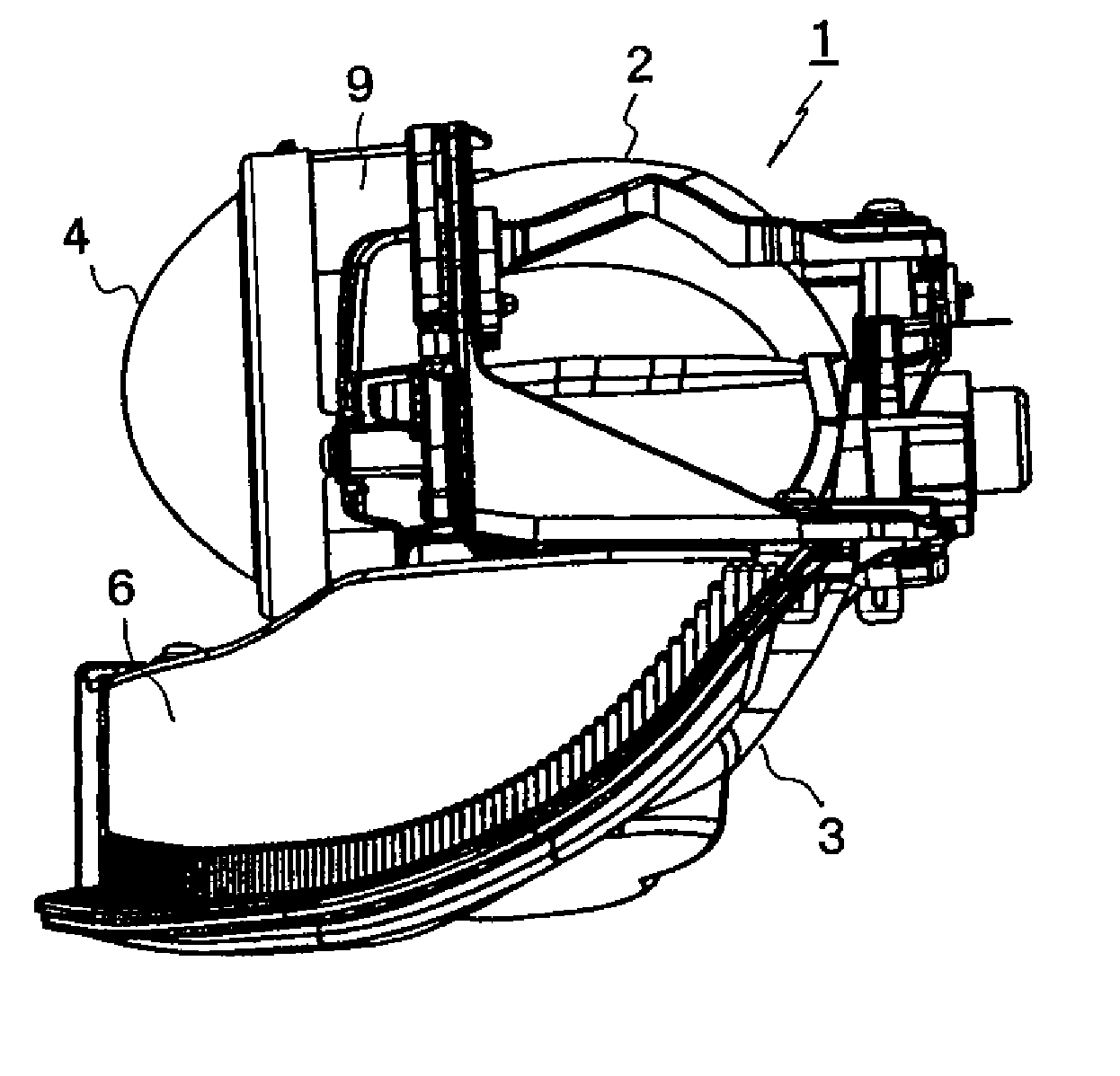
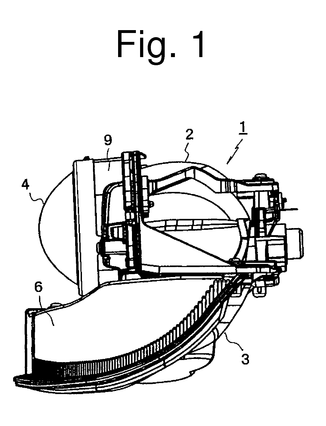
[0017]A description will now be made below to vehicle headlamps of the presently disclosed subject matter with reference to the accompanying drawings in accordance with exemplary embodiments.

[0018]It should be noted that in the present specification, the directions with regard to the “up,”“down,”“right,”“left,”“front,” and “rear” and the like may be based on the case where the vehicle light is installed in a vehicle body. Namely, the directions may be considered to match to the vertical direction (up-to-down direction), the lateral direction (right-to-left or vehicle width direction), and the front-to-rear direction of the vehicle body.

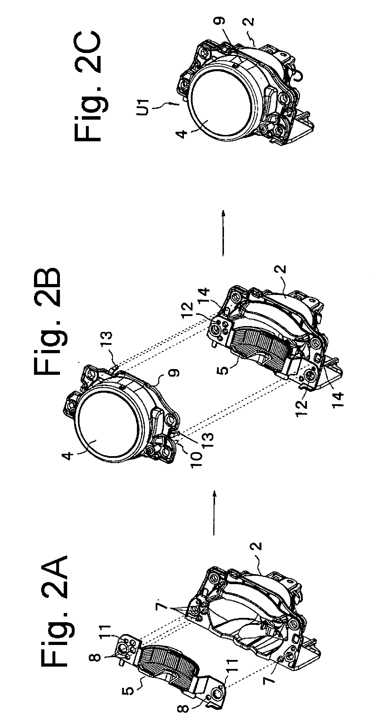
[0019]FIG. 1 is a side view of a vehicle headlamp made in accordance with principles of the presently disclosed subject matter. FIGS. 2A, 2B, and 2C and 3A, 3B, and 3C are perspective views illustrating assembly processes for the vehicle headlamp. Furthermore, FIG. 4 is a table illustrating combinations of the first and second reflectors and the shade...


PUM

PropertyMeasurementUnit
areasaaaaaaaaaa
areaaaaaaaaaaa
shapesaaaaaaaaaa

Abstract

A vehicle lamp can include a light source, a first reflector and a second reflector configured to reflect light from the light source, a convex lens disposed in front of the first reflector, and a shade configured to partially shield the light reflected by the first reflector. One component (e.g., second reflector) out of the first reflector, the second reflector and the shade can be assembled to be brought into contact with another component (e.g., shade) out of the first reflector, the second reflector and the shade at respective contact areas of the one component and the other component according to a particular specification. The second reflector and the shade can have corresponding erroneous-assembly prevention members at corresponding positions of respective contact areas, respectively, so that a different second reflector according to a different specification can be prevented from mating with the shade according to the particular specification, and a different shade according to a different specification is prevented from mating with the second reflector according to the particular specification.

Description

[0001]This application claims the priority benefit under 35 U.S.C. §119 of Japanese Patent Application No. 2009-261431 filed on Nov. 17, 2009, which is hereby incorporated in its entirety by reference.TECHNICAL FIELD[0002]The presently disclosed subject matter relates to a vehicle lamp, and specifically to a vehicle headlamp having first and second reflectors and a shade.BACKGROUND ART[0003]Conventional vehicle headlamps have included a shade for shielding light that is directed from a light source to an opposite / oncoming vehicle in order to prevent or suppress the occurrence of “glare light” to a driver of the opposite / oncoming vehicle(s) or pedestrian(s). (See, for example, Japanese Patent Application Laid-Open Nos. 2000-149638 (or U.S. Pat. No. 6,471,384B1 corresponding to this JP application) and 2008-098030.) One example thereof can include a light source, a first reflector and a second reflector for reflecting light from the light source, and a shade for partially shielding li...

Claims


Application Information

Patent Timeline
Patent Type & Authority Applications(United States)
IPC IPC(8): B60Q1/04B23P11/00
CPCF21S48/1216F21S48/1305Y10T29/49826F21V17/007F21S48/142F21S41/295F21S41/39F21S41/47
Inventor TSUKAGOSHI, TADAOKONOKI, RYOJITAKAHASHI, YUTA
Owner STANLEY ELECTRIC CO LTD
Features
  • R&D
  • Intellectual Property
  • Life Sciences
  • Materials
  • Tech Scout
  • Unparalleled Data Quality
  • Higher Quality Content
  • 60% Fewer Hallucinations
Learn More