Ablation catheter with transducer for providing one or more of pressure, temperature and fluid flow data for use in controlling ablation therapy

a technology of transducer and catheter, which is applied in the field of electrophysiological (“ ep”) catheter system, can solve the problems of affecting the normal rhythm of the heart, affecting the normal flow of blood flow,

Inactive Publication Date: 2005-10-18
CARDIAC PACEMAKERS INC
View PDF14 Cites 199 Cited by
  • Summary
  • Abstract
  • Description
  • Claims
  • Application Information

AI Technical Summary

Problems solved by technology

Improper growth, remodeling, or damage to, the conductive tissue in the heart can interfere with the passage of regular electrical signals from the SA and AV nodes.
Electrical signal irregularities resulting from such interference can disturb the normal rhythm of the heart and cause an abnormal rhythmic condition referred to as “cardiac arrhythmia.”
While this procedure has been found to be successful, it involves an intensely invasive approach.
In both the unipolar and the bipolar methods, the current traveling between the electrodes of the catheter and between the electrodes and the backplate enters the tissue and induces a temperature rise in the tissue resulting in ablation.
While this electrode / tissue contact assessment technique is effective for the treatment of focal arrhythmias, it is less effective for the treatment of non-focal arrhythmias, such as atrial fibrillation.
The presence of blood against a portion of the band electrode affects the impedance measurement and reduces the significance of the difference between the blood-pool impedance and the contact-assessment impedance.
Thus, the above-described electrode / tissue contact assessment technique that relies on the use of a tip electrode forced into the tissue is ineffective for linear ablation therapy.
This known technique is further ineffective for linear ablation because it does not account for fluctuations in impedance measurements which may occur due to movement of electrodes caused by respiration and heart contractions.
Blood coagulation is a major limitation / complication associated with RF ablation therapy.
Coagulation can lead to thromboembolism and also form an insulating layer around the electrode hindering further energy delivery required for ablation therapy.
Low blood flow results in reduced convective heat dissipation within the blood pool around the electrode and thus higher blood temperature.
Conversely, high blood flow rate results in increased convective heat dissipation within the blood pool around the electrode and thus a lower blood temperature.
Conventional RF ablation systems fail to account for the effect that varying blood flow rates have on blood, electrode and tissue temperatures, which can be substantial.
Such systems tend either to have a high incidence of coagulation or to operate inefficiently.
The temperature sensing thermocouple does not provide the system with sufficient information about the temperature of the blood pool.
Over the course of an ablation procedure, the cumulative effect of the periods of low-blood flow is likely to result in coagulum formation.
This, however, tends to lead to an inefficient ablation procedure.
The culmination of these periods of non-ablative temperature levels at best increases the amount of time necessary to achieve an ablation-inducing temperature and thus the overall procedure time, and at worst prevents the electrode from ever reaching an ablation-inducing level.

Method used


Image

  • Ablation catheter with transducer for providing one or more of pressure, temperature and fluid flow data for use in controlling ablation therapy
  • Ablation catheter with transducer for providing one or more of pressure, temperature and fluid flow data for use in controlling ablation therapy
  • Ablation catheter with transducer for providing one or more of pressure, temperature and fluid flow data for use in controlling ablation therapy

Examples


Embodiment Construction

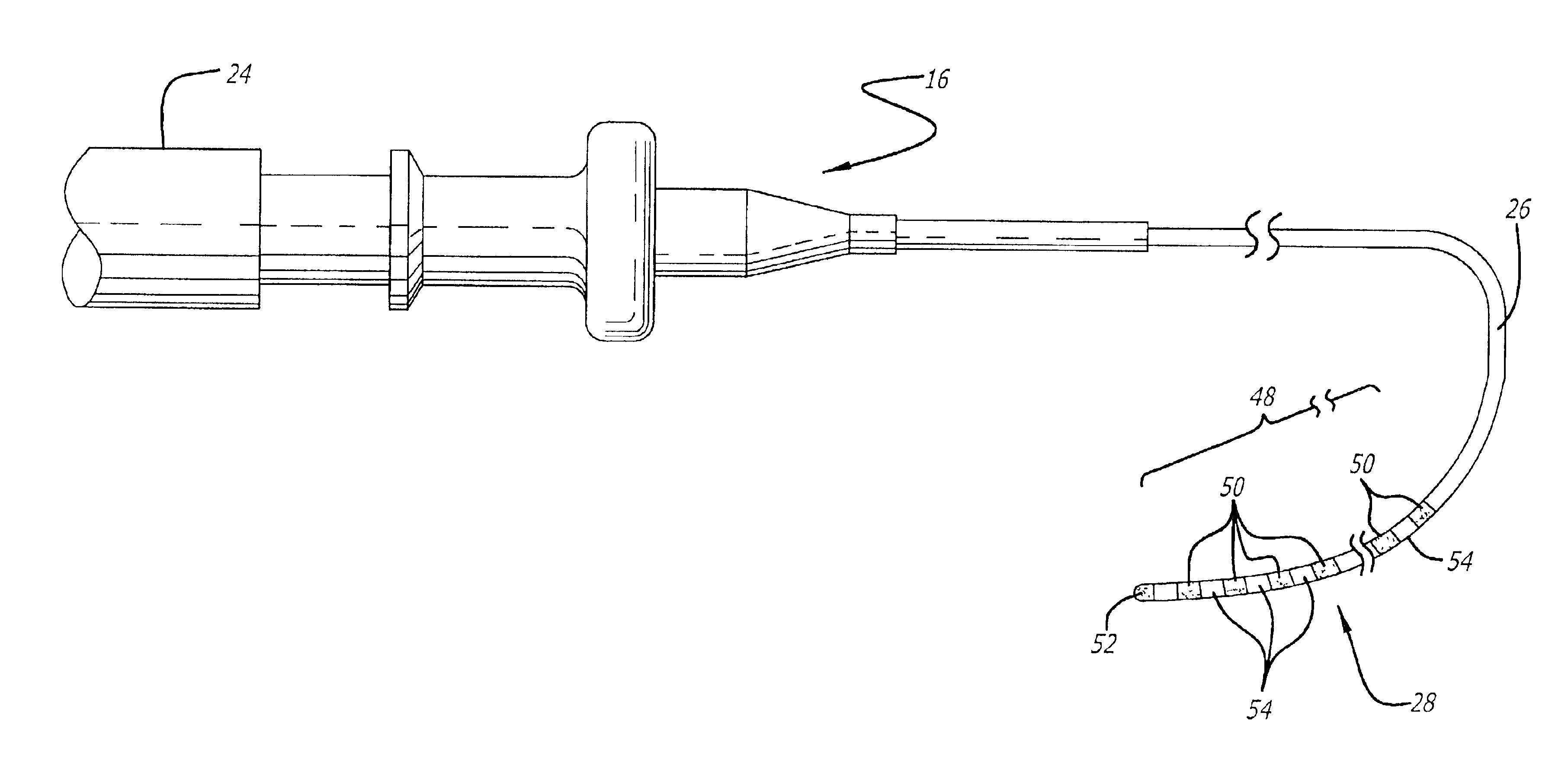
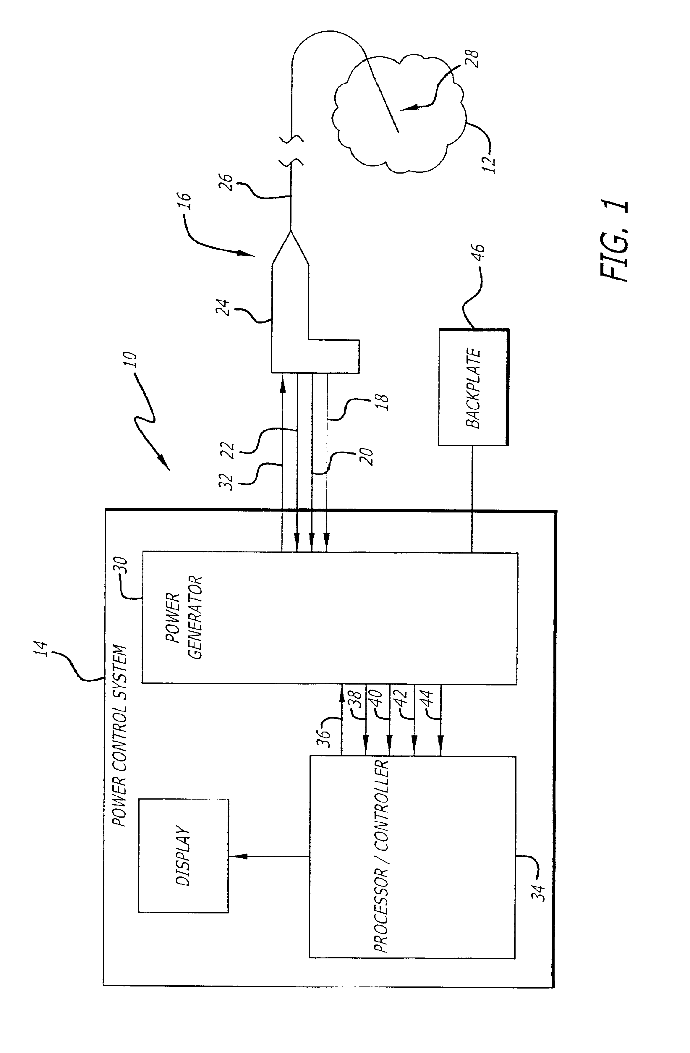
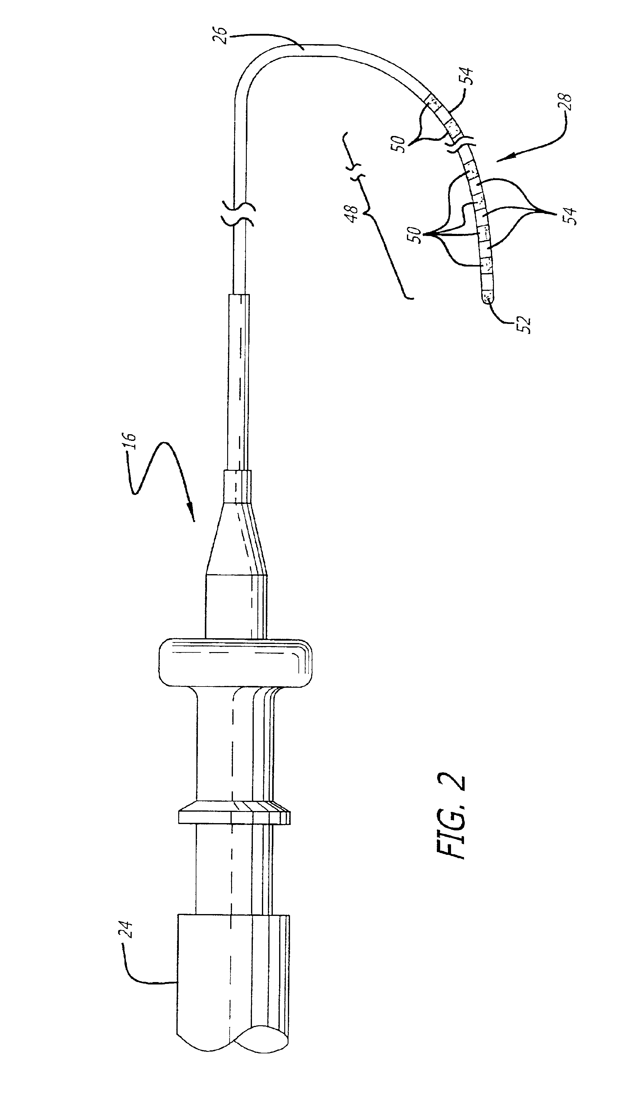
[0045]Turning now to the drawings, in which like reference numerals are used to designate like or corresponding elements among the several figures, in FIG. 1 there is shown a system 10 for use in ablation therapy of a biological site 12, e. g., the atrium or ventricle of the heart. The system 10 includes a power control system 14, a catheter system 16 having means (not shown) for providing one or more of pressure data 18, flow-rate data 20 and temperature data 22 to the power control system 14. The catheter system 16 includes a handle 24 and a steerable catheter shaft 26 having a distal segment28. The distal segment 28 carries an electrode system (not shown) and is capable of being percutaneously introduced into a biological site 12. The pressure data 18 includes data indicative of the pressure being exerted on the distal segment 28 in the region of the electrode system while the flow-rate data 20 includes data indicative of the rate of fluid flow through the biological site 12, suc...


PUM


Abstract

A distal segment of a catheter shaft is adapted to be positioned against tissue in a biological organ. The distal segment has a tissue-contacting area intended to contact the tissue. One or more pressure sensors positioned within the tissue-contacting area provide pressure data indicative of the pressure exerted on the distal segment. The distal segment carries one or more electrodes and the pressure sensors are located either on an electrode or on the catheter shaft near an electrode. The pressure sensors provide pressure data to a processor that analyzes the data to determine if the tissue-contacting area of the distal segment is contacting the tissue. The pressure sensors may also provide temperature data indicative of the temperature at the sensor. A flow sensor, located opposite the pressure sensor on the shaft, provides data related to the flow rate of fluid through the organ.

Description

RELATED APPLICATIONS[0001]This is a continuation-in-part of application Ser. No. 09 / 797,435, filed Mar. 1, 2001 now U.S. Pat. No. 6,666,862.BACKGROUND OF THE INVENTION[0002]1. Field of the Invention[0003]The invention relates generally to an electrophysiological (“EP”) catheter system and method for providing energy to biological tissue within a biological site, and more particularly, to an EP system and method for assessing the adequacy of contact between the catheter and tissue and controlling the delivery of RF energy to the tissue based on the flow of fluid through the biological site.[0004]2. Description of the Related Art[0005]The heart beat in a healthy human is controlled by the sinoatrial node (“SA node”) located in the wall of the right atrium. The SA node generates electrical signal potentials that are transmitted through pathways of conductive heart tissue in the atrium to the atrioventricular node (“AV node”) which in turn transmits the electrical signals throughout the...

Claims


Application Information

Patent Timeline
Patent Type & Authority Patents(United States)
IPC IPC(8): A61B18/14
CPCA61B18/1492A61B18/16A61B2018/0016A61B2018/00351A61B2018/00577A61B2018/00654A61B2018/00714A61B2018/00726A61B2018/00779A61B2018/00791A61B2018/00797A61B2018/00839A61B2018/00863A61B2018/124A61B2018/1253A61B2018/1273A61B2018/1286A61B2018/1467A61B2019/465A61B2090/065
Inventor JAIN, MUDIT K.
Owner CARDIAC PACEMAKERS INC
Why Eureka
Try Eureka