Temperature control in image forming apparatus
- Summary
- Abstract
- Description
- Claims
- Application Information
AI Technical Summary
Benefits of technology
Problems solved by technology
Method used
Image

Examples
Embodiment Construction
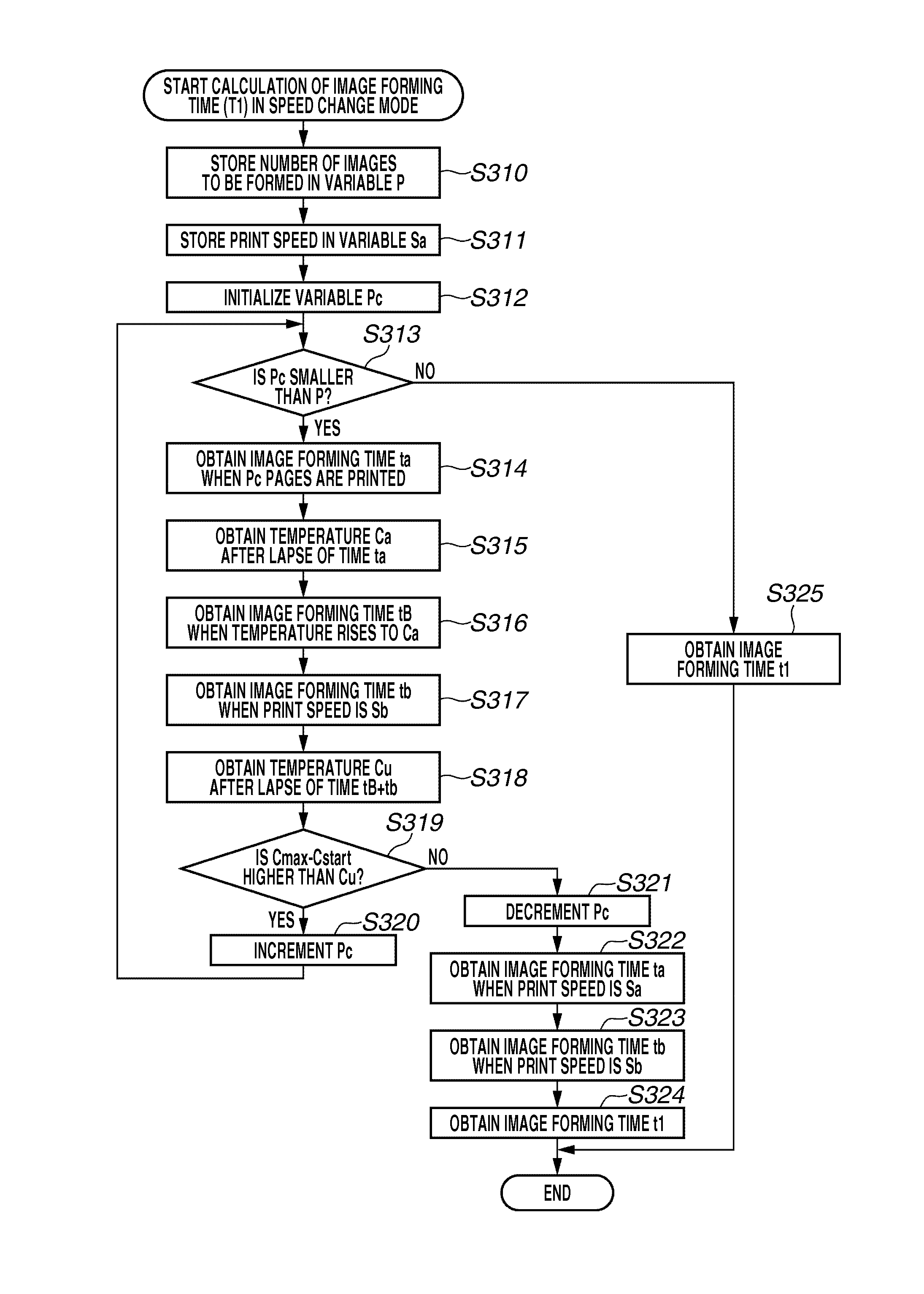
[0029]Various exemplary embodiments, features, and aspects of the invention will be described in detail below with reference to the drawings. The following embodiments are not intended to limit the invention described in the claims thereof, and all combinations of characteristic features described in the embodiments are not necessarily essential to the solving means of the invention.
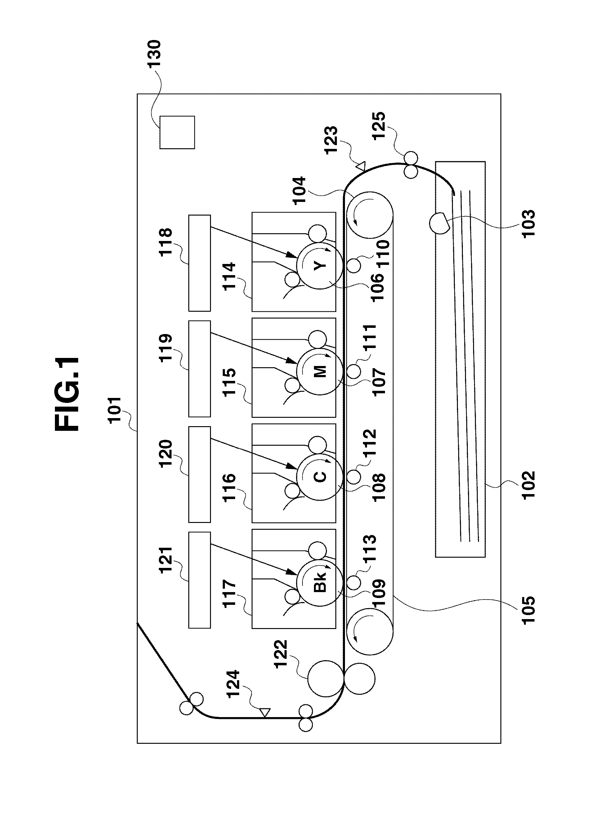
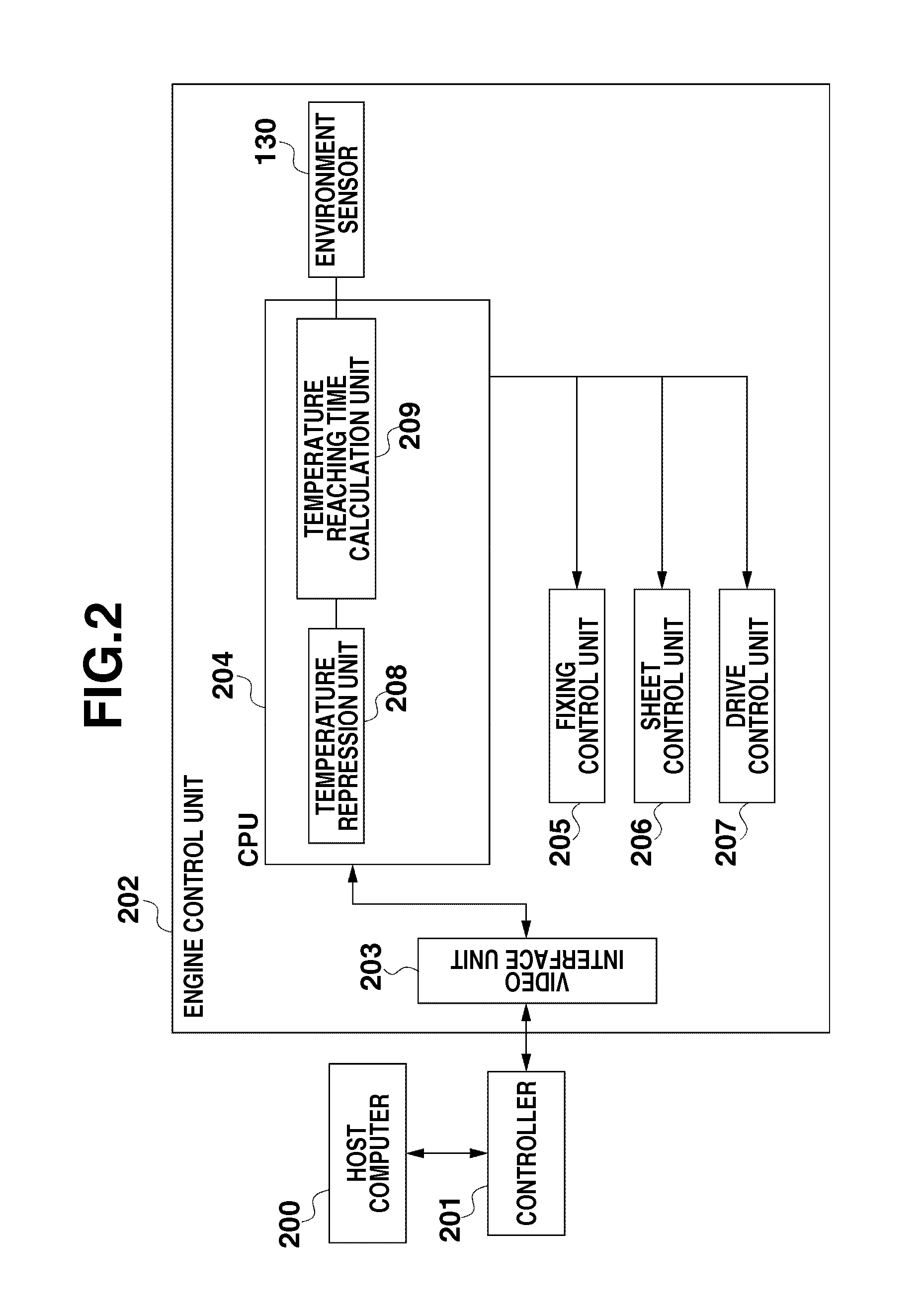
[0030]FIG. 1 is a schematic diagram of an image forming apparatus 101 according to a first exemplary embodiment of the invention. A sheet feed tray 102 contains recording medium. A sheet feeding roller 103 picks up a recording medium from the sheet feed tray 102. A drive roller 104 drives a transfer belt 105. Photosensitive drums 106 to 109 have images formed on their surfaces, and transfer rollers 110 to 113 transfer the images on the photosensitive drums to a recording medium. Cartridges 114 to 117 each accommodate a toner container containing a toner to form an image, and a developing roller to develo...
PUM
 Abstract
Description
Claims
Application Information