Systems and Methods for Dynamic Pneumatic Valve Driver

a pneumatic valve and dynamic technology, applied in the field of pneumatic surgical systems, can solve the problems of blurred vision, complex surgical machine used for vitrectomy and other surgeries on the posterior of the eye, and other problems, to achieve the effect of improving the safety and safety of patients

Active Publication Date: 2011-06-16
ALCON INC
View PDF98 Cites 46 Cited by
  • Summary
  • Abstract
  • Description
  • Claims
  • Application Information

AI Technical Summary

Benefits of technology

[0011]In various embodiments, a pneumatic system valve for a surgical console may be controlled by a controller configured to adjust a valve duty cycle (VDC) (the VDC being used to energize the valve) to reduce a difference between a differential pressure (e.g., an average differential pressure) at the valve's output and a desired differential pressure (e.g., a desired average differential pressure). In some embodiments, average differential pressures may be detected and relayed from a pressure sensor, coupled to one or more ports of the valve, to the controller (e.g., implementing a PID controller (Proportional-Integral-Derivative controller) algorithm). The controller may compare the measured average differential pressure against the desired average differential pressure (e.g., received from the user or determined based on information received from the user). The controller may then determine a modified VDC to reduce a difference between the desired average differential pressure and the measured average differential pressure. In some embodiments, multiple iterations may be performed to reduce the difference between the measured average differential pressure and the desired average differential pressure.

Problems solved by technology

Blood, inflammatory cells, debris, and scar tissue may obscure light as it passes through the eye to the retina, resulting in blurred vision.
The surgical machine used to perform a vitrectomy and other surgeries on the posterior of the eye is very complex.

Method used


Image

  • Systems and Methods for Dynamic Pneumatic Valve Driver
  • Systems and Methods for Dynamic Pneumatic Valve Driver
  • Systems and Methods for Dynamic Pneumatic Valve Driver

Examples


Embodiment Construction

[0021]U.S. Patent Application Publication entitled “Pneumatic System for a Vitrector,” Publication No. 20080149197, Ser. No. 11 / 614,678, by Denis Turner, Robert Palino, Argelio Olivera, and Mark Hopkins filed Dec. 21, 2006 is hereby incorporated by reference in its entirety as though fully and completely set forth herein.

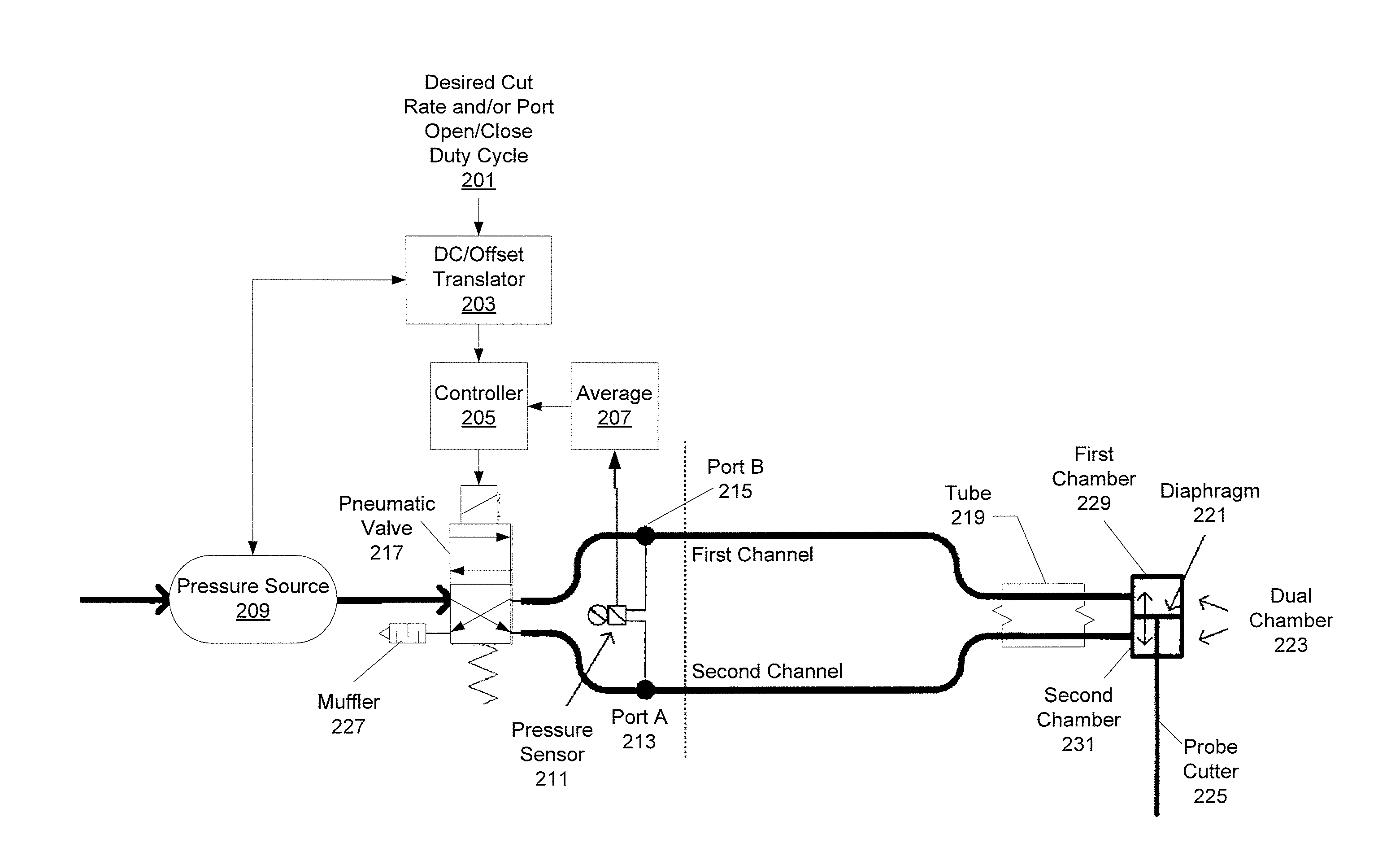
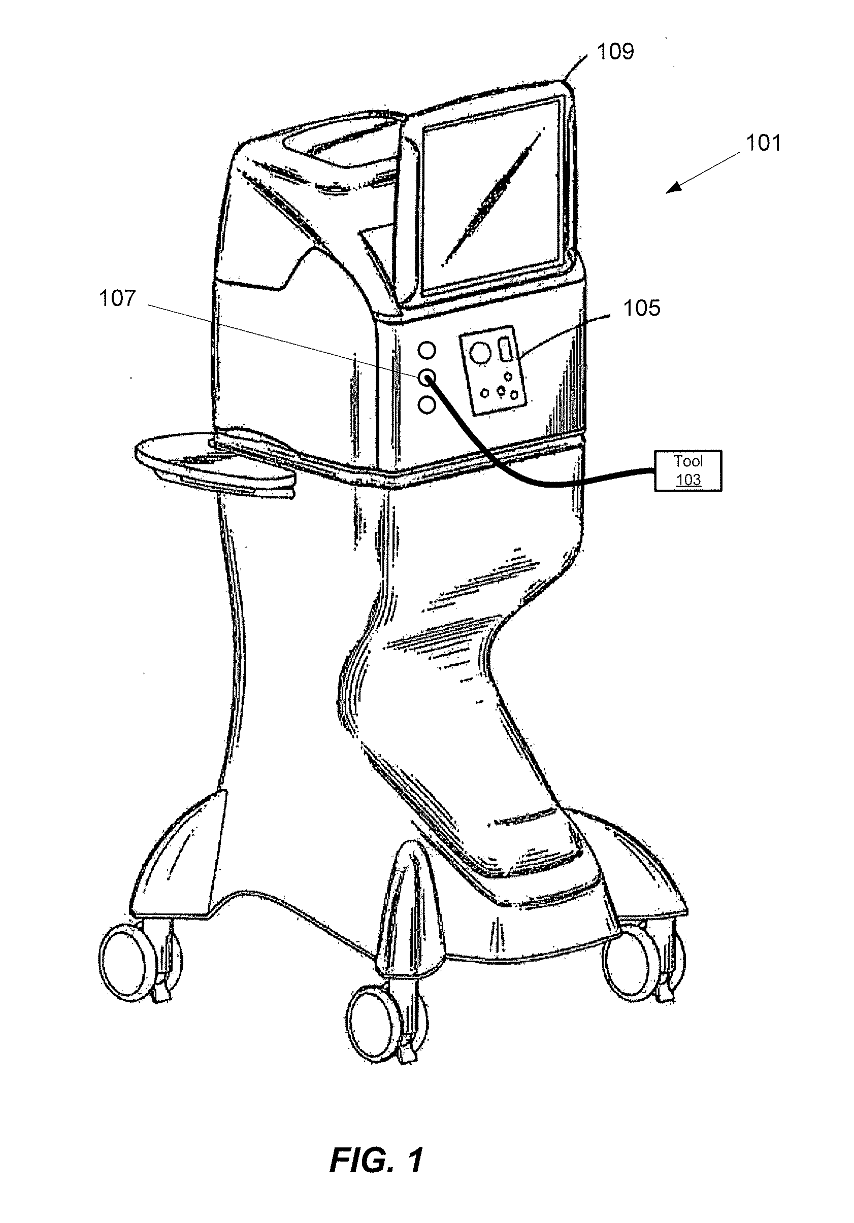
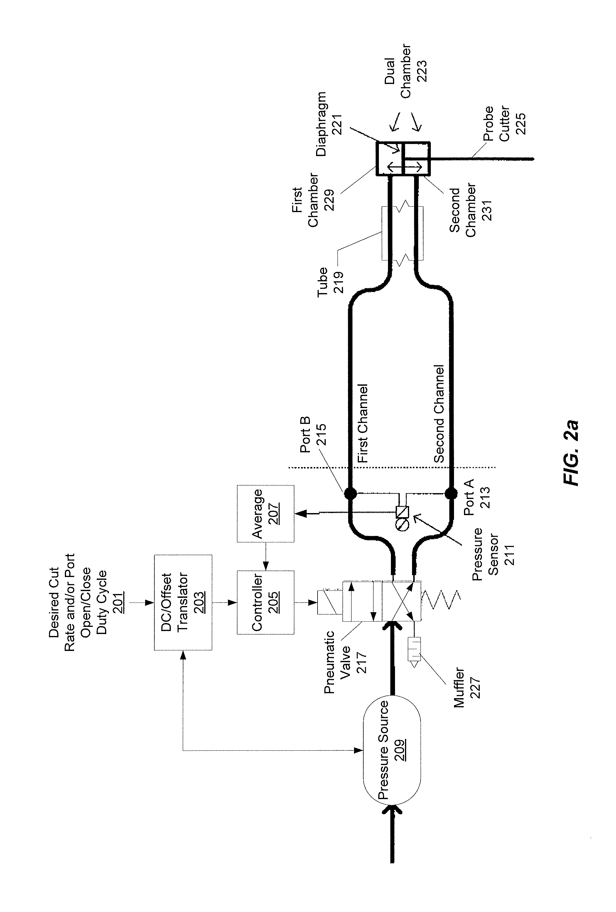
[0022]FIG. 1 illustrates an embodiment of a surgical console 101 for a pneumatically powered ophthalmic surgical machine. The surgical console 101 may be configured to drive one or more pneumatic tools 103. The tools 103 may include, for example, scissors, vitrectors, forceps, and injection or extraction modules. Other tools 103 may also be used. In operation, the pneumatically powered ophthalmic surgery machine of FIG. 1 may operate to assist a surgeon in performing various ophthalmic surgical procedures, such as a vitrectomy. A compressed gas, such as nitrogen, may provide the power through the surgical console 101 to power tools 103. The surgical console 101 may ...


PUM


Abstract

In various embodiments, a pneumatic system valve for a surgical console may be controlled by a controller configured to adjust a valve duty cycle (VDC) of the valve to reduce a difference between the valve's differential pressure and a desired differential pressure. In some embodiments, average differential pressures may be detected and relayed from a pressure sensor, coupled to one or more ports of the valve, to the controller. The controller may compare the measured average differential pressure against the desired average differential pressure (e.g., received from the user). The controller may then determine a modified VDC to reduce a difference between the desired average differential pressure and the measured average differential pressure. In some embodiments, the desired average differential pressure may be determined based on input received from a user of the surgical console.

Description

PRIORITY[0001]This application claims the benefit of priority of U.S. Provisional Patent Application Ser. No. 61 / 285,243 titled “Systems and Methods for Dynamic Pneumatic Valve Driver”, filed on Dec. 10, 2009, whose inventors are Shawn X. Gao and Mark A. Hopkins, which is hereby incorporated by reference in its entirety as though fully and completely set forth herein.FIELD OF THE INVENTION[0002]The present invention generally pertains to a pneumatic surgical system. More particularly, but not by way of limitation, the present invention pertains to surgical system pneumatic generation.DESCRIPTION OF THE RELATED ART[0003]Vitreo-retinal procedures may include a variety of surgical procedures performed to restore, preserve, and enhance vision. Vitreo-retinal procedures may be appropriate to treat many serious conditions of the back of the eye. Vitreo-retinal procedures may treat conditions such as age-related macular degeneration (AMD), diabetic retinopathy and diabetic vitreous hemorrh...

Claims


Application Information

Patent Timeline
Patent Type & Authority Applications(United States)
IPC IPC(8): A61F9/007
CPCA61F2009/00874A61F9/00736Y10T137/7761
Inventor GAO, SHAWN X.HOPKINS, MARK ALAN
Owner ALCON INC
Why Eureka
Try Eureka