Failure Detection and Fencing in a Computing System

a technology of failure detection and computing system, applied in the field of failure detection and fencing in a computing system, can solve problems such as delay of several seconds or more, significant delay, and event-based techniques experiencing significant delays

Inactive Publication Date: 2011-06-16
IBM CORP
View PDF9 Cites 21 Cited by
  • Summary
  • Abstract
  • Description
  • Claims
  • Application Information

AI Technical Summary

Problems solved by technology

These techniques have significant drawbacks, for example, polling requires extra CPU cycles to perform the polling (e.g., the CPU cycles associated with sending and responding to the messages), and experiences a significant delay in the detection of the death of the system, and event-based techniques may experience significant delays before the event is generated.
For example, a SIGCHLD is typically not generated until all diagnostic information necessary for root cause analysis of the error (e.g., core dumps and other dumps) are complete, which can result in a delay of several seconds or more.

Method used


Image

  • Failure Detection and Fencing in a Computing System
  • Failure Detection and Fencing in a Computing System
  • Failure Detection and Fencing in a Computing System

Examples


Embodiment Construction

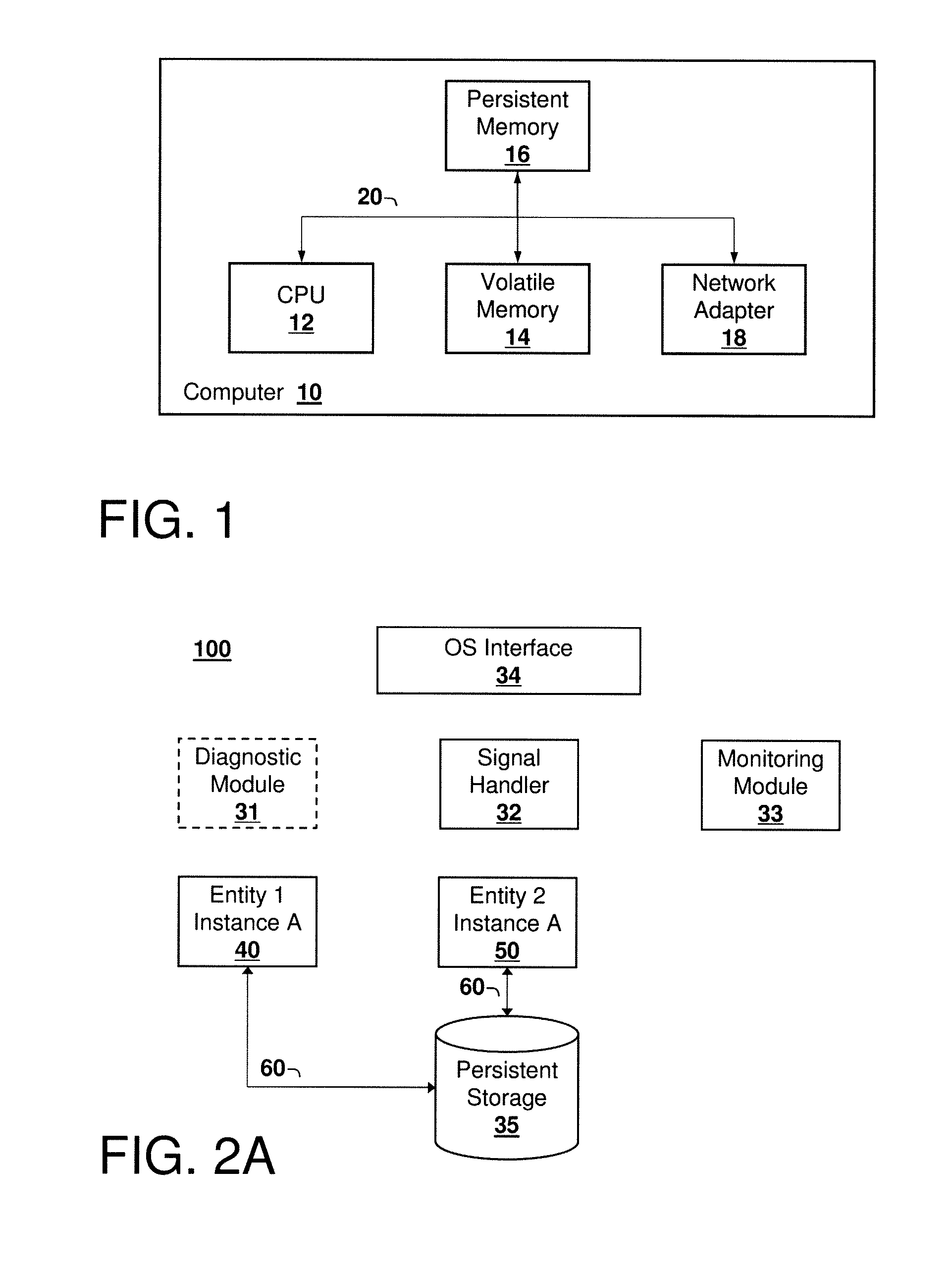
[0011]Referring now to the Figures, an exemplary computer system according to embodiments of the present invention is illustrated in FIG. 1. FIG. 1 shows a computer system 10 comprising processor 12, volatile memory 14, persistent or non-volatile memory 16, and network adapter 18, all communicatively coupled together by system bus 20. The system 10 may include additional servers, clients, and other devices not shown, and individual components of the system may occur either singly or in multiples, for example, there may be more than one data storage area in the system. The system 10 may also be a node, for example a node in a computing cluster, which is connected to other nodes by suitable means, for example via a network.

[0012]The computer system 10 may be implemented in the form of a processing system, or may be in the form of software. The computer system 10 may be implemented by any quantity of conventional or other computer systems or devices (e.g., computer terminals, personal ...


PUM


Abstract

A method, computer program product, and system for detecting and fencing off a failed entity instance so that failover time in the computing system is reduced. Upon detection of a failed entity, for example a failed process, a signal handler invokes an operating system interface to fence off the failed instance from modifying its persistent state, so that the entity may be re-instantiated prior to termination of the failed instance. This approach reduces failover time and eliminates split-brain problems without compromising access to the failed instance to obtain diagnostic information, core dumps, and the like.

Description

BACKGROUND[0001]1. Technical Field[0002]The present invention relates generally to failure detection and fencing in a computing system, and more particularly to detecting and fencing off a failed entity instance so that failover time in the computing system is reduced.[0003]2. Discussion of Related Art[0004]Many computing systems maintain important state information on persistent media. For example a database system typically stores the actual data of the database in persistent media. When such systems experience a critical failure, it is desirable to restart the system as quickly as possible, either on the same host computer, or on a different computer that has access to the same persistent media. The overall goal is to minimize the period of time that the system is unavailable for use by end users (known as “failover time”). Mechanisms used to automate this failure recovery include polling techniques to determine if the system is healthy, and event-based techniques that generate a...

Claims


Application Information

Patent Timeline
Patent Type & Authority Applications(United States)
IPC IPC(8): G06F11/07
CPCG06F11/0793G06F11/0715
Inventor BUCKLER, ANDREW DAVIDGARCIA-ARELLANO, CHRISTIAN MARCELOHEPKIN, DAVID ALANHURAS, MATTHEW ALBERTSACHEDINA, AAMER
Owner IBM CORP
Why Eureka
Try Eureka