Dimension measuring device for long material

a measurement device and long material technology, applied in the direction of measurement devices, mechanical diameter measurements, instruments, etc., can solve the problems of long time required and reduce pipe production efficiency, and achieve the effects of reducing the measurement error caused by vibration, enhancing the dimensional measurement accuracy of long material, and high accuracy

Active Publication Date: 2011-06-23
NIPPON STEEL CORP
View PDF7 Cites 9 Cited by
  • Summary
  • Abstract
  • Description
  • Claims
  • Application Information

AI Technical Summary

Benefits of technology

[0011]The present invention has been made to solve the problems with the prior art, and accordingly an objective thereof is to provide a dimension measuring device capable of automatically measuring the dimensions of a long material such as a pipe, which may be bent in the end portion thereof, with high accuracy.
[0012]As means for grasping the direction and position of the reference plane of the long material (the plane passing through the endmost point in the longitudinal direction of the long material of the points constituting the end face in the longitudinal direction of the long material), it is conceivable that the shape of the end face is measured by using optical means such as a laser range finder, and the endmost point is detected from the obtained end face shape to grasp the direction and position of the reference plane passing through the endmost point. However, in the case where the long material is a pipe having a small wall thickness, since the dimension in the radial direction of the end face is small in a cross section passing through the center axis of pipe, when the cross-sectional shape in the radial direction of the end face is measured by using the optical means, there arises a need to grasp an approximate position, at which the end face exists, by any means in advance. Also, even if the approximate position at which the end face exists could be grasped, in the case where the cross-sectional shape in the radial direction of the end face is not flat but curved as shown in FIGS. 6A and 6B, much time is required to detect the endmost point. To grasp the direction and position of the reference plane, it is necessary to detect at least three endmost points constituting the end face and to three-dimensionally calculate the reference plane passing through the at least three endmost points. Therefore, very long time is required to grasp the direction and position of the reference plane, and the pipe production efficiency is decreased.
[0013]Accordingly, the present inventors paid attention to the fact that an end face following mechanism that butts against the end face in the longitudinal direction of the long material is used as means for grasping the position and direction of the reference plane without decreasing the production efficiency of long material. The present inventors carried out studies earnestly, and resultantly conceived of an end face following mechanism that includes a plurality of (three or more) contact sensors, which are arranged along one plane to detect the contact state, on the side where the end face following mechanism butts against the end face in the longitudinal direction of the long material, and is turnable around at least two axes intersecting at right angles with the direction normal to the plane and intersecting at right angles with each other. This end face following mechanism is pushingly moved toward the end face in the longitudinal direction of the long material and is butted against the end face, whereby in the case where the long material has been bent in the end portion thereof, the end face following mechanism turns following the end face in the longitudinal direction regardless of the direction of the bend. Also, if the end face following mechanism is pushingly moved into the state in which at least three contact sensors of the plurality of contact sensors detect that the end face following mechanism butts against the end face (the endmost point of end face) in the longitudinal direction of long material, the end face following mechanism can be butted surely against the end face. The present inventors came up with the idea that if the configuration is made such that a dimension measuring mechanism for measuring the dimensions of the long material can be pushingly moved integrally and be turned integrally with the end face following mechanism, even in the case where the long material has been bent in the end portion thereof, by pushingly moving the end face following mechanism toward the end face in the longitudinal direction of the long material and causing the mechanism to butt against the end face, the dimension measuring mechanism is also pushingly moved integrally with the end face following mechanism, and turns integrally with the end face following mechanism according to the bend of the end portion, so that the dimensions at the predetermined positions in the direction perpendicular to the reference plane can be measured with high accuracy.

Problems solved by technology

Therefore, very long time is required to grasp the direction and position of the reference plane, and the pipe production efficiency is decreased.

Method used


Image

  • Dimension measuring device for long material
  • Dimension measuring device for long material
  • Dimension measuring device for long material

Examples


example 1

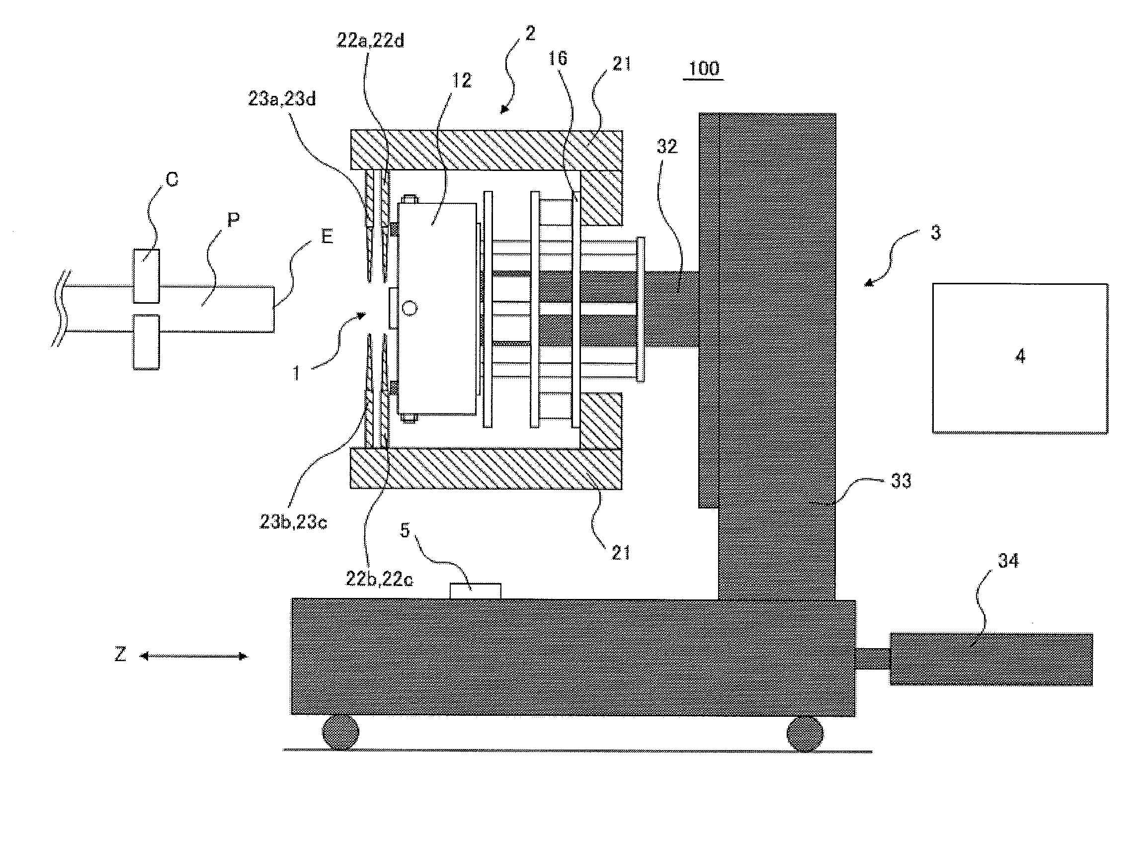
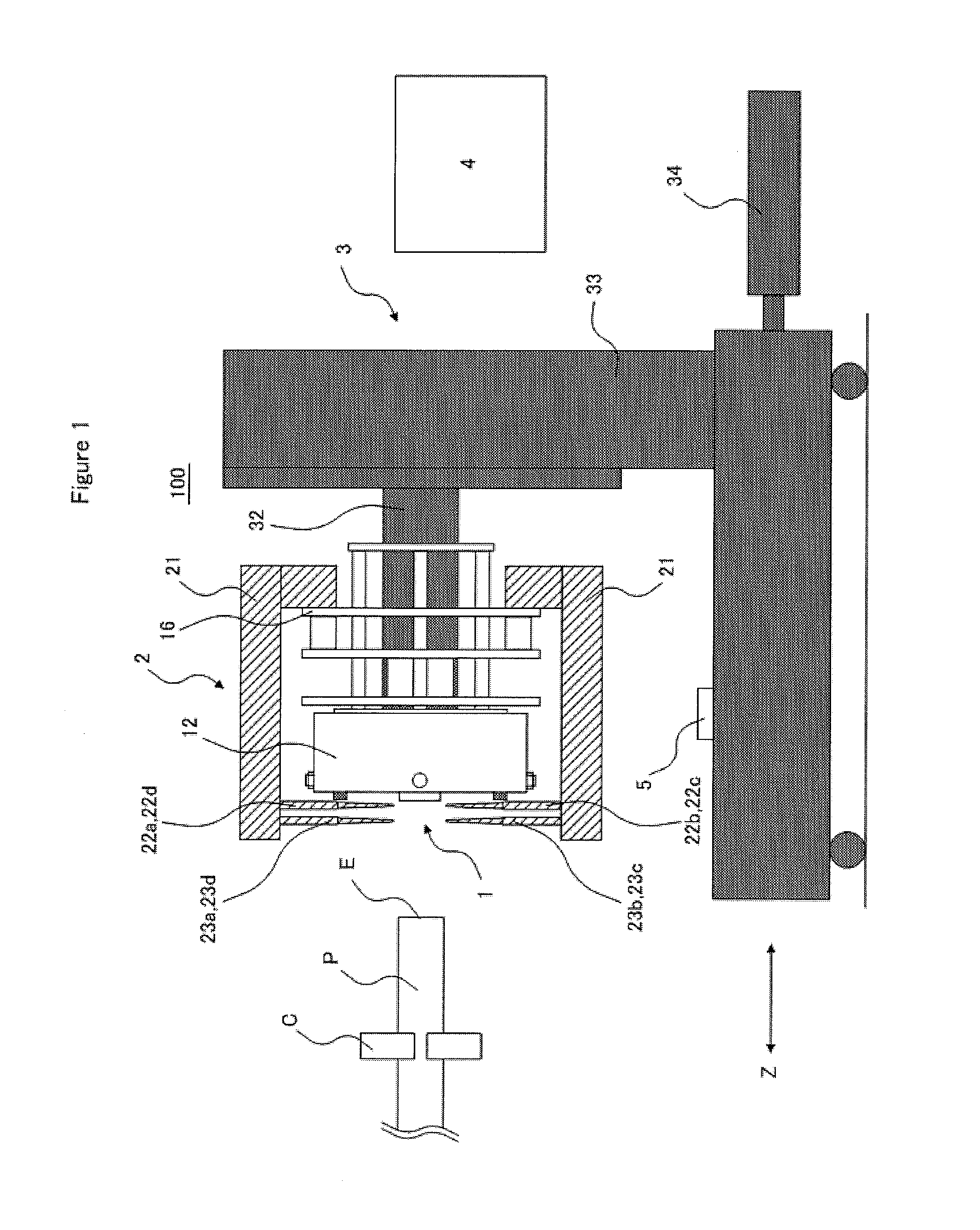
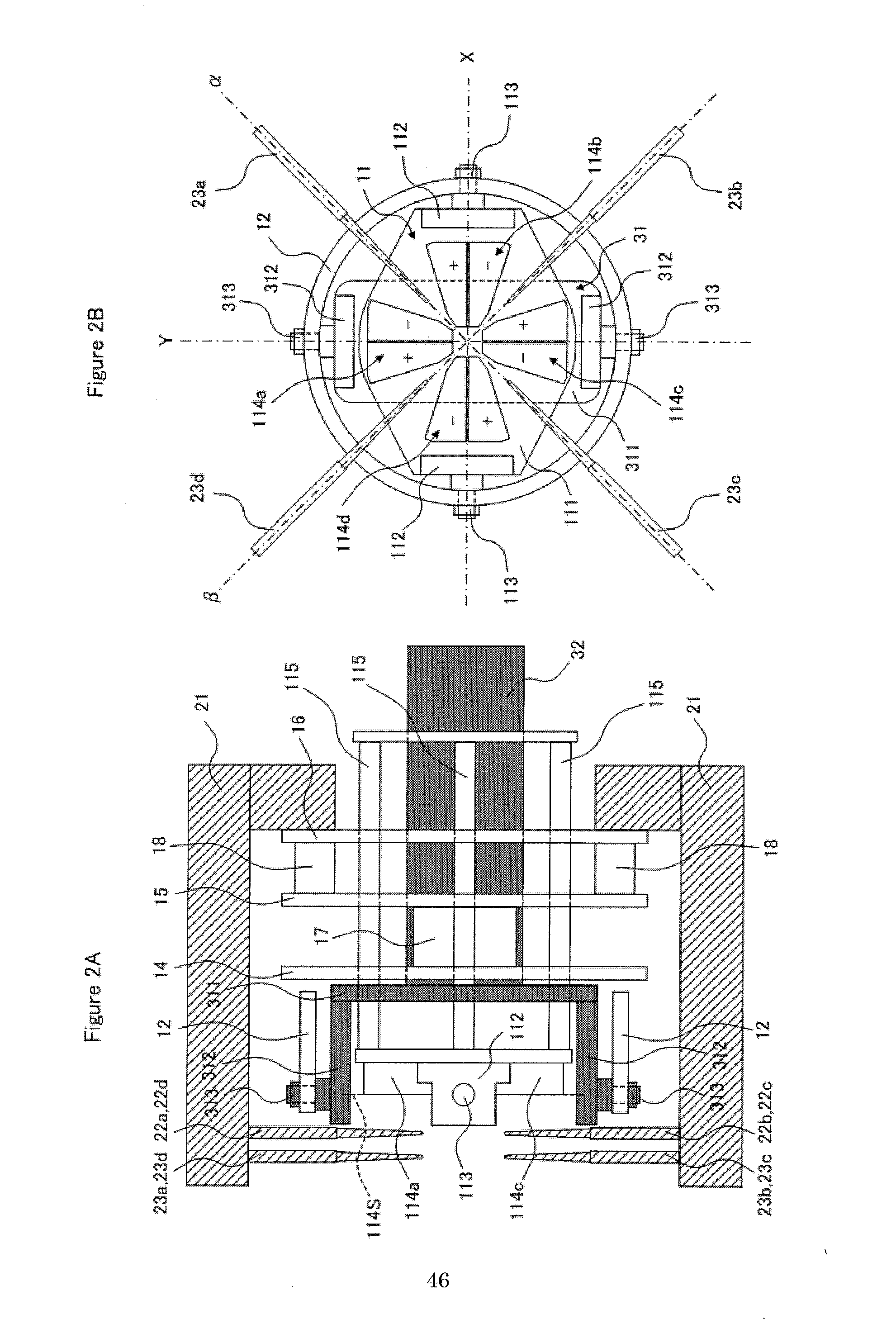
[0067]The seal diameter and the thread diameter of the pin joint formed in the end portion of the pipe P were measured by using the dimension measuring device 100 the general configuration of which is shown in FIG. 1 and FIGS. 2A and 2B. The pipe P to be measured had an outside diameter of 73.0 mm, a wall thickness of 5.51 mm, and a length of 9500 mm. A portion about 500 mm distant from the end face of the pipe P was restrained by the chuck member C, and the axial direction of the restrained portion of the pipe P was made approximately parallel to the pushingly moving direction of the end face following part 11. The bend amount of the end portion of the pipe P (=a shift amount of the cross section center of the pipe P / a length of the shift amount measuring portion) was 1.2 mm / 1000 mm at a maximum in the β-axis direction. The measurement position of seal diameter (distance SL, refer to FIGS. 6A and 6B) was 1.9 mm distant from the reference plane, and the measurement position of threa...

example 2

[0069]The seal diameter and the thread diameter of the pin joint formed in the end portion of the pipe P were measured under the same conditions as those of example 1 except that the bend amount of the end portion of the pipe P to be measured was 2.1 mm / 1000 mm at a maximum in the α-axis direction. The difference between the seal diameter and thread diameter measured as described above and the seal diameter and thread diameter measured manually by using the special-purpose measuring instrument was used as an evaluation result.

example 3

[0071]The seal diameter and the thread diameter of the pin joint formed in the end portion of the pipe P were measured under the same conditions as those of example 1 except that the bend amount of the end portion of the pipe P to be measured was 2.8 mm / 1000 mm at a maximum in the β-axis direction. The difference between the seal diameter and thread diameter measured as described above and the seal diameter and thread diameter measured manually by using the special-purpose measuring instrument was used as an evaluation result.


PUM


Abstract

A dimension measuring device 100 in accordance with the present invention includes an end face following mechanism 1 that butts against an end face E of a long material, a dimension measuring mechanism 2 for measuring the dimensions of the long material, and a pushingly moving mechanism 3 for pushingly moving the end face following mechanism toward the end face of the long material. The end face following mechanism includes a plurality of contact sensors for detecting a contact state, and is turnable around two axes intersecting at right angles with each other. The pushingly moving mechanism pushingly moves the end face following mechanism into the state in which the plurality of contact sensors detect that the end face following mechanism butts against the end face of the long material. The dimension measuring mechanism is pushingly moved integrally and is turnable integrally with the end face following mechanism, and measures the dimensions of the long material when it is detected, by the plurality of contact sensors, that the end face following mechanism butts against the end face of the long material.

Description

TECHNICAL FIELD[0001]The present invention relates to a dimension measuring device capable of accurately measuring the dimensions of a long material such as a pipe or tube that has been bent in the end portion thereof. Hereinafter, “pipe or tube” is referred to as “pipe” when deemed appropriate.BACKGROUND ART[0002]Pipes such as Oil Country Tubular Goods (OCTG) and pipes for pipeline are often used in a connected state at the end portions thereof by a joint part consisting of a so-called pin joint and box joint. Specifically, the end portion of the outer peripheral surface of the pipe is threaded and beveled to form the pin joint. A pair of pin joints formed on a pair of pipes are fastened to the box joint threaded and beveled on the inner peripheral surface thereof, whereby the pair of pipes are connected to each other. If the pin joint has a low dimensional accuracy, the pin joint and the box joint in a fastened state loosen, and therefore, pipes may be disconnected and drop, or in...

Claims


Application Information

Patent Timeline
Patent Type & Authority Applications(United States)
IPC IPC(8): G01B5/08
CPCG01B5/08G01B21/10G01B5/163G01B5/0009G01B21/047
Inventor TANIDA, MUTSUMIMATSUURA, TAKASHIKASA, YASUHISA
Owner NIPPON STEEL CORP
Why Eureka
Try Eureka