Projected capacitive touch panel

Inactive Publication Date: 2011-06-23
MINLEAD
View PDF3 Cites 11 Cited by
  • Summary
  • Abstract
  • Description
  • Claims
  • Application Information

AI Technical Summary

Benefits of technology

An objective of the present invention is to provide a projected capacitive touch panel

Problems solved by technology

However, the added masking cover not only increases the production cost but also thi

Method used


Image

  • Projected capacitive touch panel
  • Projected capacitive touch panel
  • Projected capacitive touch panel

Examples


Embodiment Construction

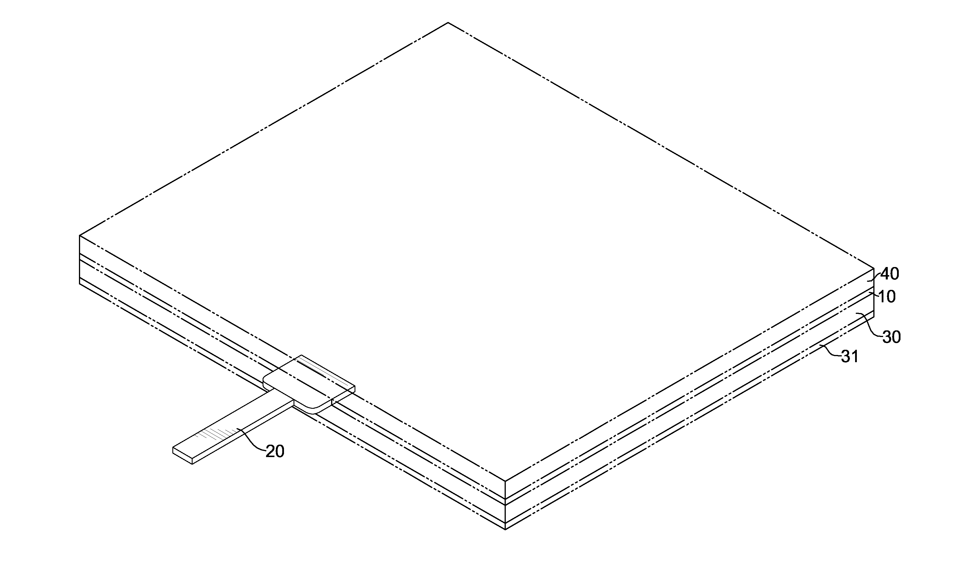
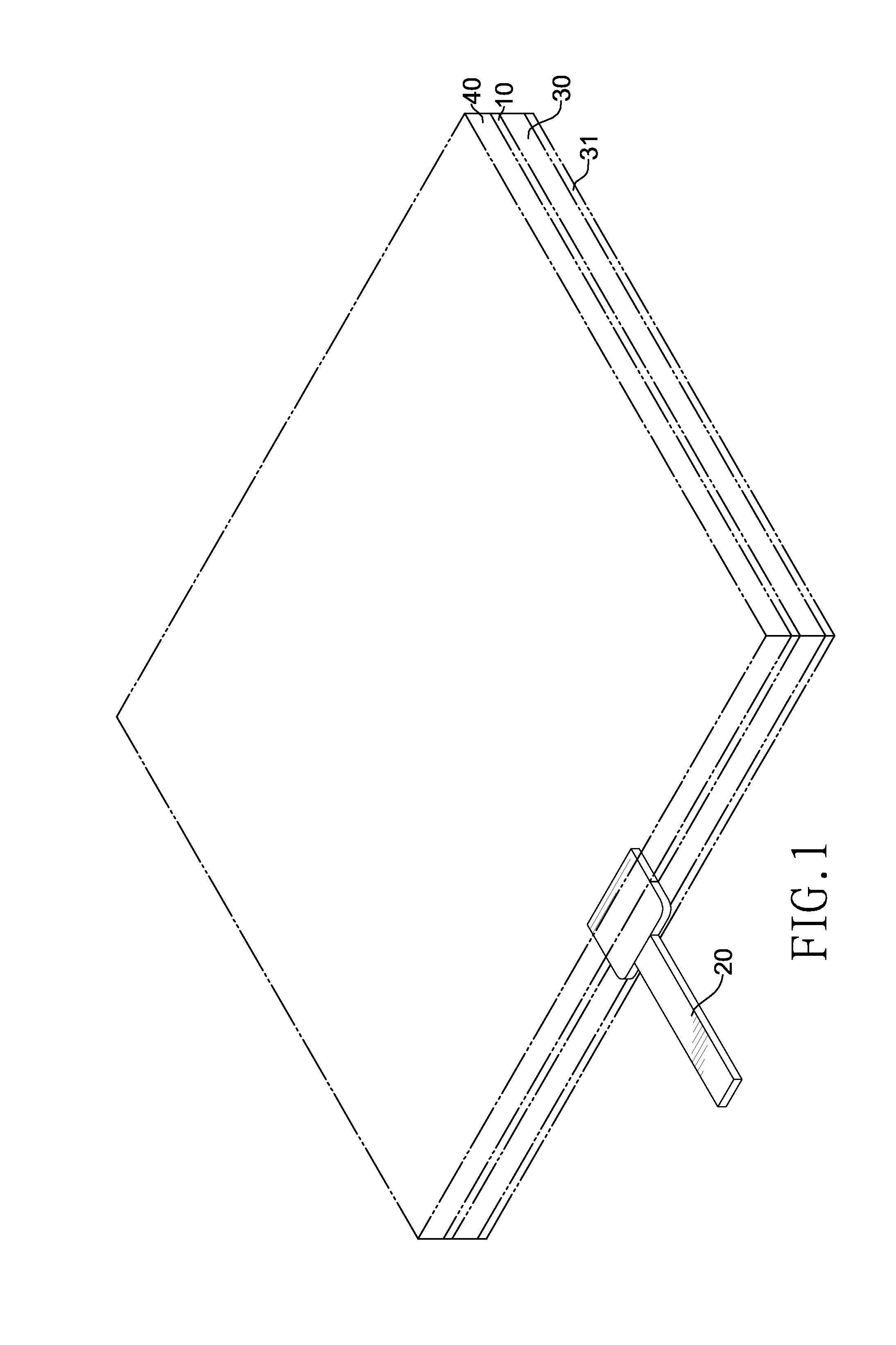
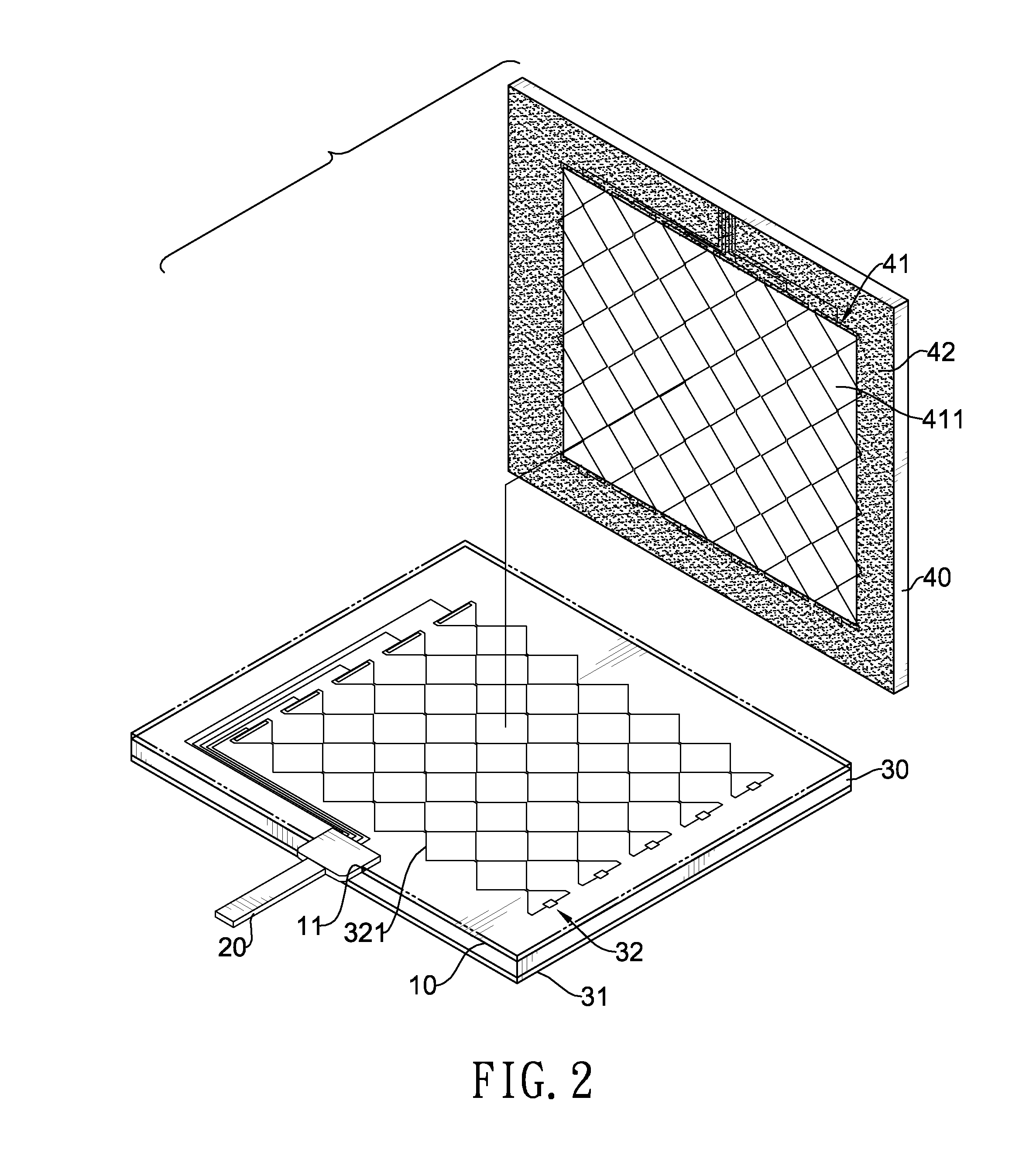
With reference to FIGS. 1 and 2, a projected capacitive touch panel in accordance with the present invention has an insulating layer 10, a flexible printed circuit board (PCB) 20, a lower substrate 30 and an upper substrate 40.

The insulating layer 10 has a recess 11 formed in one edge thereof.

The flexible PCB 20 is mounted in the recess 11 of the insulating layer 10.

With reference to FIG. 3, technically, the structure of the lower substrate 30 is identical to those of conventional projected capacitive touch panels. The lower substrate 30 is mounted on bottoms of the insulating layer 10 and the flexible PCB 20, and has an electromagnetic shielding layer 31, multiple lower conducting layers 32, multiple lower ports 33 and multiple lower wires 34. The electromagnetic shielding layer 31 is formed on a bottom of the lower substrate 30 and is composed of ITO. The lower conducting layers 32 are parallelly formed on a top of the lower substrate 30, and align in a first direction. Each lower...


PUM


Abstract

A projected capacitive touch panel has an upper substrate and a lower substrate. The upper substrate has multiple upper conducting layers, and each upper conducting layer has multiple upper sensor units serially connected. The upper substrate further has an insulating ink layer being non-transparent, formed on a perimeter of the bottom of the upper substrate, covering an edge of the upper sensor unit located on one end of each upper conducting layer in a direction, overlapping with the lower ports and the lower wires of the lower substrate, and having multiple reserved slots, each formed through a portion of the insulating ink layer overlapping with a corresponding upper sensor unit, and multiple conductors, each mounted in a corresponding reserved slot. The insulating ink layer masks the wires and ports on the lower and upper substrates, thereby eliminating the use of a masking cover, saving the cost and thinning the product.

Description

BACKGROUND OF THE INVENTION1. Field of the InventionThe present invention relates to a touch panel, and more particularly to a projected capacitive touch panel eliminating the use of a masking cover for masking wires and ports on the substrates.2. Description of the Related ArtBased on technical concept, touch panels can be classified into capacitive touch panels, resistive touch panels, surface acoustic touch panels, infrared touch panels and the like. Among them, the capacitive touch panels are advantageous in being waterproof and abrasion-resistant and having higher light transmittance, and are mainly applied to high-grade displays. Specifically, the capacitive touch panels can be further divided into surface capacitive touch panels and projected capacitive touch panels. As the projected capacitive touch panels serve for multi-touch operation, they are extensively applied to audio and video products nowadays.The projected capacitive touch panels are usually composed of two substr...

Claims


Application Information

Patent Timeline
IPC IPC(8): H03K17/975
CPCH03K2217/960755G06F3/044G06F3/0446G06F3/0445G06F2203/04103
Inventor HSU, JANE
Owner MINLEAD
Why Eureka
Try Eureka