

Auxiliary fuel tank system
- Summary
- Abstract
- Description
- Claims
- Application Information
AI Technical Summary
Benefits of technology
Problems solved by technology
Method used
Image

Examples
Embodiment Construction
[0022]The present invention is illustrated in further details by the following non-limiting examples.
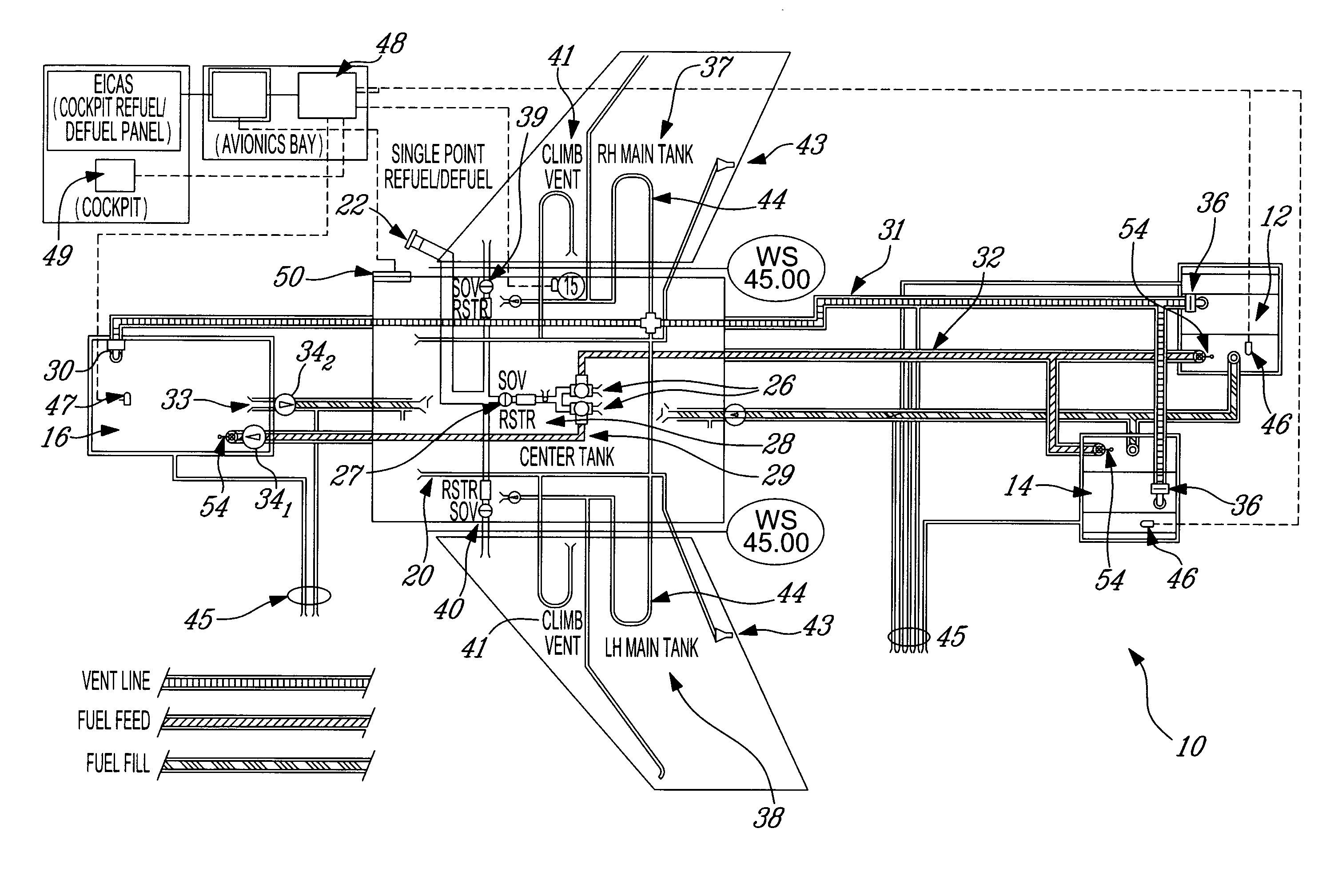
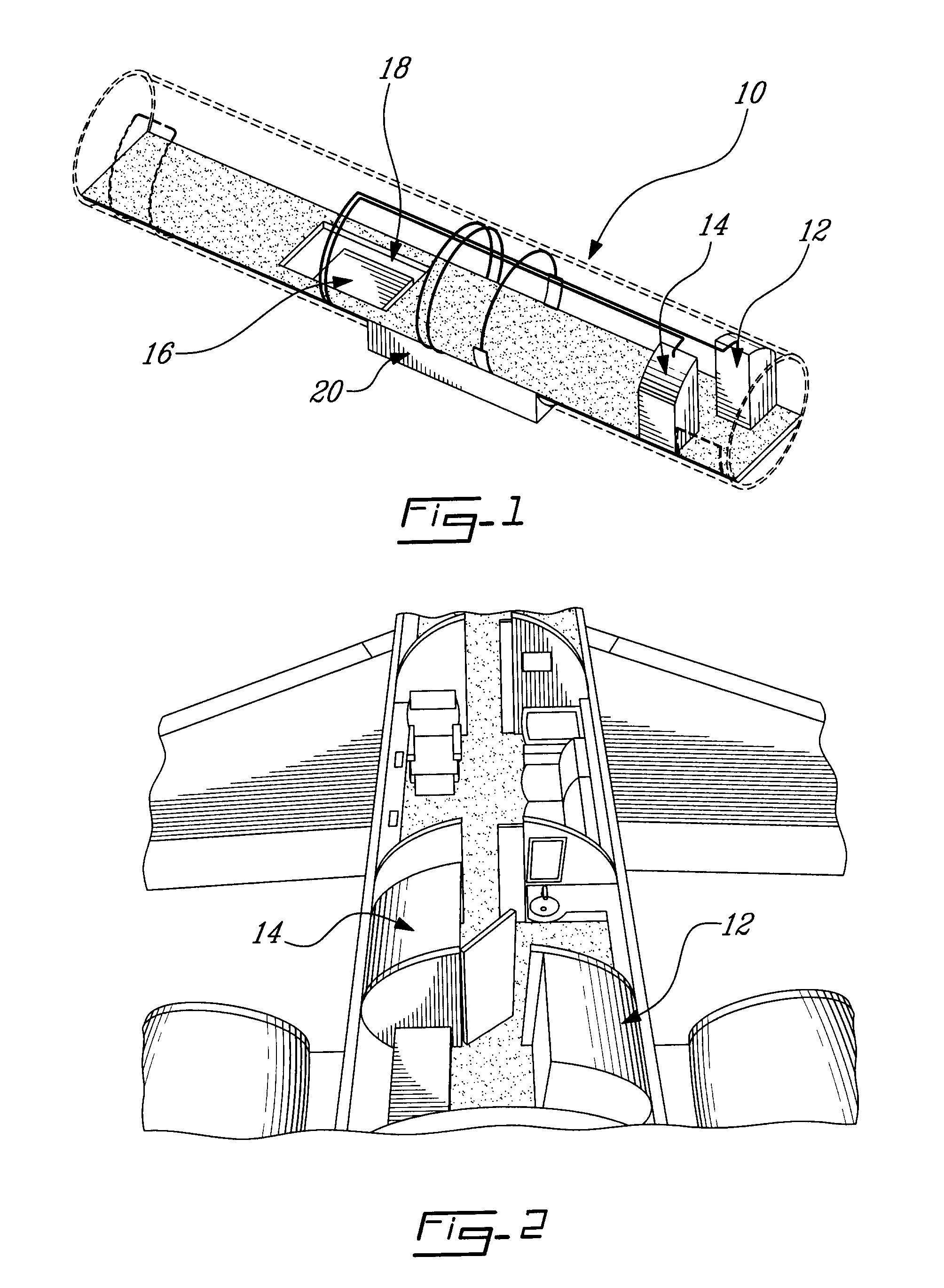
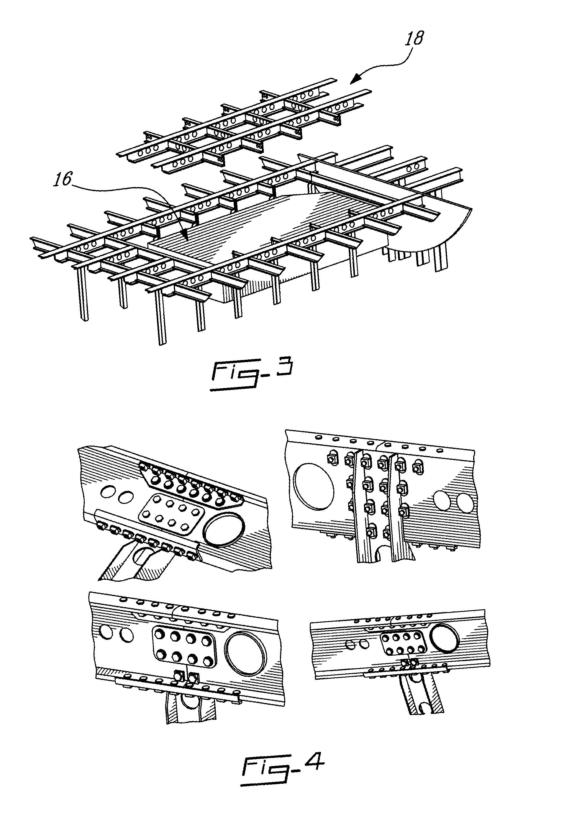
[0023]Referring to FIG. 1, the auxiliary fuel tank system, generally referred to using reference numeral 10, will be further described. The auxiliary fuel tanks are referred to using numerals 12, 14 and 16. Auxiliary fuel tank 16 is illustratively installed at the front and below a removable floor module 18. The main or center wing tank 20 is the aircraft's existing fuel tank.
[0024]Referring now to FIG. 2, the positioning of the rear auxiliary fuel tanks 12 and 14 inside the aircraft can be seen. These fuel tanks are illustratively installed above the aircraft floor level and occupy a space defined between the ceiling, the floor and the sidewall of the aircraft, leaving space for a middle lane. Fuel tanks 12 and 14 are installed in a staggered configuration which results in larger usable cabin space, easier access to the baggage compartment, and better weight distribution on the floo...
PUM
 Abstract
Description
Claims
Application Information