Air inlet valve for an airplane and manufacturing method for an air inlet valve

a technology of air intake valve and air intake valve, which is applied in the direction of machines/engines, other domestic articles, energy-saving board measures, etc., can solve the problems of ineffective determination and inflow of air that cannot be effectively determined

Inactive Publication Date: 2011-06-23
AIRBUS OPERATIONS GMBH
View PDF6 Cites 5 Cited by
  • Summary
  • Abstract
  • Description
  • Claims
  • Application Information

AI Technical Summary

Benefits of technology

[0009]The object of the invention is therefore to provide a solution for a flow-optimised air intake valve of an aircraft which is arranged in the region of a submerged air inlet, with which the aircraft is fitted to equalise inversely-acting differential air pressures. The air intake valve is to ensure a self-regulating, free passage of air into the inner region of the aircr...

Problems solved by technology

The inflow of this air is not optimised by the adjustment of any measures.
In this respect, it is a disadvantage that the actual air flow which enters the aircraft fuselage via these mentioned valves under inverse pressure c...

Method used


Image

  • Air inlet valve for an airplane and manufacturing method for an air inlet valve
  • Air inlet valve for an airplane and manufacturing method for an air inlet valve
  • Air inlet valve for an airplane and manufacturing method for an air inlet valve

Examples


embodiment 1

[0070] Air intake valve for an aircraft, comprising:

[0071]an opening region for letting ambient air through into a fuselage inner region of the aircraft,

[0072]a flap for opening and closing the opening region,

[0073]characterised in that the opening region and the flap each have a shape which is capable of forming air vortices on edges of the opening region when ambient air flows through the air intake valve.

[0074]Embodiment 2: Air intake valve according to embodiment 1, characterised in that the opening region and the flap each have an NACA shape which is capable of forming self-enlarging air vortices on the edges of the opening region when ambient air flows through the air intake valve.

embodiment 3

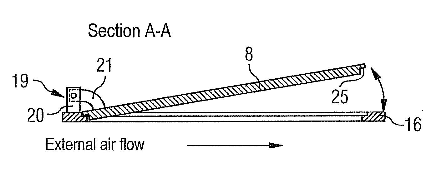
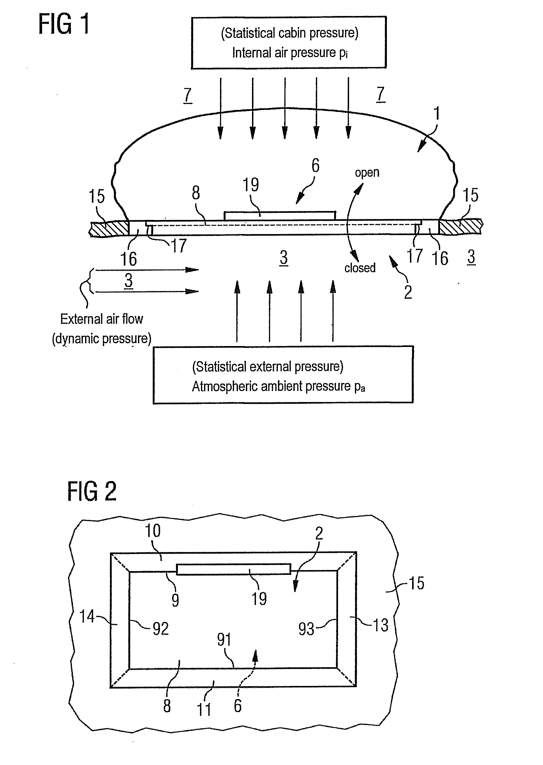
[0075] Air intake valve according to at least one of the preceding embodiments, characterised in that the air intake valve is positioned in the region of an NACA submerged air inlet with which an air pressure equalisation is provided when there is an inversely-acting differential air pressure between a pressure-ventilated inner region of an aircraft fuselage which is subjected to an internal air pressure, and an NACA submerged air inlet region which is submerged lengthwise in the downstream direction of the aircraft fuselage and is arranged inside a fuselage outer skin covering the aircraft fuselage and is connected in terms of air flow to the fuselage inner region, and an atmospheric ambient air pressure bears down on an opening region of the NACA submerged air inlet on the inlet side of the NACA submerged air inlet region, which opening region is restricted by a side frame and which is covered by the flap in the rest position, the flap closing the opening region, if the ambient ai...

embodiment 4

[0076] Air intake valve according to at least one of the preceding embodiments, characterised in that the flap is attached to a first transverse side of the side frame which is disposed transversely to the fuselage longitudinal axis upstream of the aircraft fuselage, which flap is mounted rotatably in the region of the attachment site.

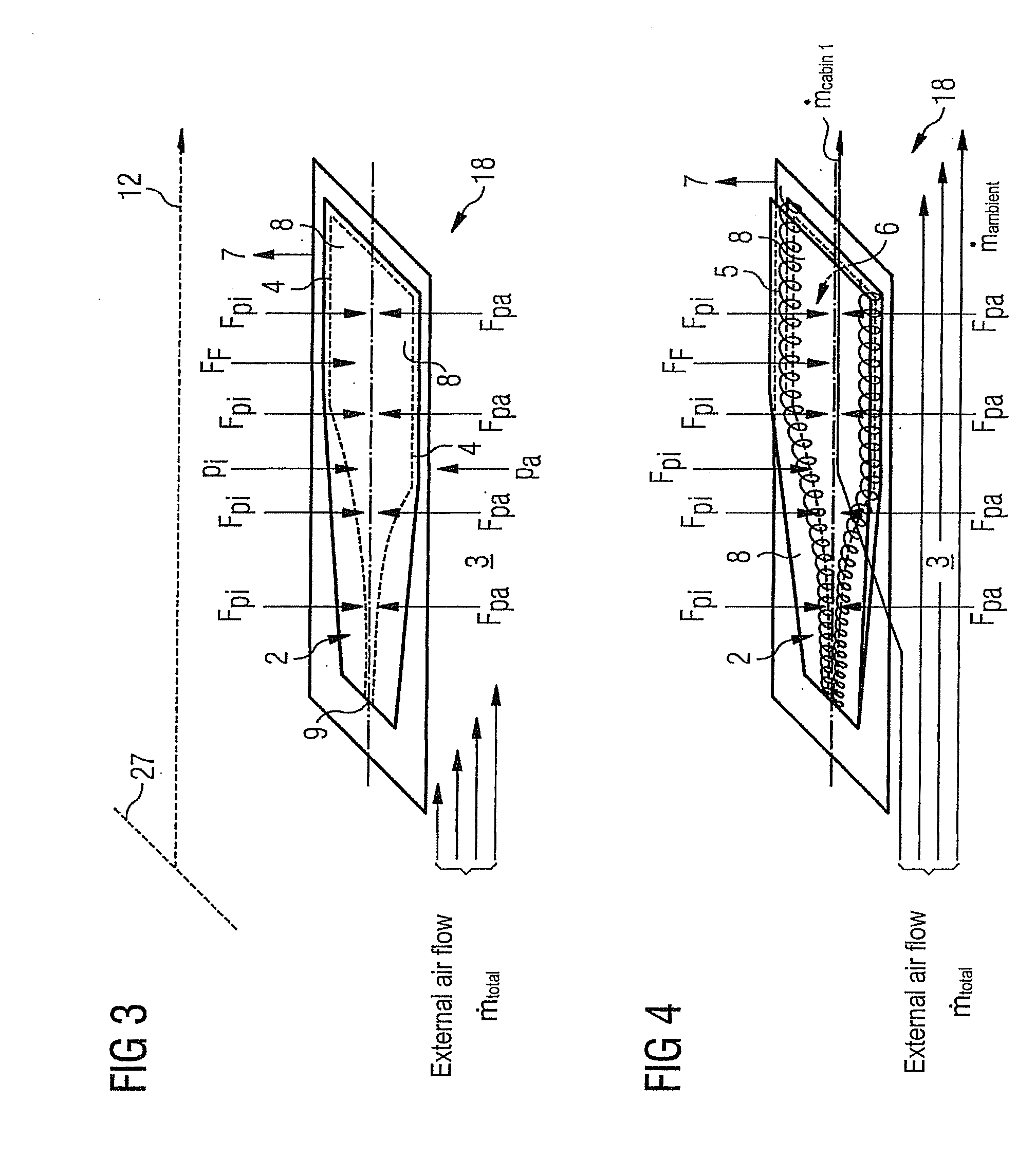
[0077]Embodiment 5: Air intake valve according to embodiment 4, characterised in that the attachment site can be moved, as a function of the force conditions acting thereon in a manner applying air pressure, relative to the opening region connected to the fuselage inner region at the outlet of the NACA submerged air inlet region.

[0078]Embodiment 6: Air intake valve according to embodiment 5, characterised in that a flow-optimised and self-regulating air intake valve function can be implemented by means of the opening region while utilising the air vortices, arising on the ramp-side cutout edges of the NACA submerged air inlet region, of the external ai...


PUM

PropertyMeasurementUnit
Pressureaaaaaaaaaa
Angleaaaaaaaaaa
Widthaaaaaaaaaa

Abstract

The present invention provides an air intake valve for an aircraft and a method for the production of an air intake valve. The air intake valve has an opening region for letting ambient air through into a fuselage inner region of the aircraft and a flap for opening and closing the opening region, the opening region and the flap each having a shape which is capable of forming air vortices on edges of the opening region when ambient air flows through the air intake valve.

Description

CROSS-REFERENCE TO RELATED APPLICATIONS[0001]This application is a continuation of PCT / EP2009 / 056782 filed Jun. 3, 2009 and claims the benefit of U.S. Provisional Application No. 61 / 130,884, filed Jun. 4, 2008 and German Patent Application No. 10 2008 002 205.5, filed Jun. 4, 2008, the entire disclosures of which are herein incorporated by reference.FIELD OF THE INVENTION[0002]The invention relates to a flow-optimised air intake valve for an aircraft according to the preamble of claim 1 and to a method for the production of an air intake valve of this type according to the preamble of claim 26. The invention provides a flow-optimised air intake valve which is positioned in the region of a submerged air inlet and is constructed to be self-regulating under the influence of the force conditions acting thereon in an air pressure-loading manner. The use of the air intake valve produces an optimisation, adapted to the aerodynamic flow conditions, of the air flowing into the submerged air ...

Claims


Application Information

Patent Timeline
IPC IPC(8): F16K1/16B64D13/00B21K1/20
CPCB64D13/00B64D2241/00Y10T29/49412Y02T50/56Y02T50/44Y02T50/40Y02T50/50Y10T137/0536Y10T137/0645
Inventor SCHIEK, THORSTENPETRAC, MARKUSSCHERER, THOMAS
Owner AIRBUS OPERATIONS GMBH
Why Eureka
Try Eureka