

Method for stabilizing contact lenses
a technology for contact lenses and lenses, applied in the field of stabilizing contact lenses, can solve the problems of time-consuming and expensive processes
- Summary
- Abstract
- Description
- Claims
- Application Information
AI Technical Summary
Benefits of technology
Problems solved by technology
Method used
Image

Examples
example 1
[0074]A contact lens having a known design for correcting the vision of astigmatic patients is shown in FIG. 6. It was designed using conventional lens design software with the following input design parameters:[0075]Sphere power: −3.00D[0076]Cylinder Power: −0.75D[0077]Cylinder Axis: 180 deg[0078]Lens diameter: 14.50 mm[0079]Front optical zone diameter of 8.50 mm[0080]Back optical zone diameter of 11.35 mm[0081]Lens base curve: 8.50 mm[0082]Center Thickness: 0.08 mm[0083]Eye model parameters used are listed in Table 2A and 2B.
[0084]The stabilization zone is an extra thick zone added to the thickness profile of that lens. The initial stabilization zone is constructed using a combination of normalized Gauss functions describing the radial and angular changes in thickness. The mathematical expression describing the Sag of the stabilization zone in polar coordinates is:
Z(R,θ)=Z0·Exp(-0.5·(r-r0σR)2)·Exp(-0.5·(θ-θ0σθ)2)
[0085]Where Z0 is the maximum magnitude of the stabilization zone, r0...
example 2
[0103]A new stabilization zone was designed using the eye model and optimization method described above and the initial design described in Example. The merit function was defined using[0104]Surface area below the response in rotation.[0105]Surface area below the response in centration.[0106]Identical weight for rotation and centration, WR=WC=1.0.
[0107]The values from which the initial stabilization zone were built were:[0108]Z0=0.25 mm[0109]r0=5.75 mm[0110]σR=0.50 mm[0111]θ0=180 degrees and 0 degrees for left and right stabilization zones, respectively[0112]σθ=25.0 degrees
[0113]The stabilization zone was then added to the original lens thickness profile.
[0114]The stabilization zone was rotated around the peak location until the lens performance characteristics represented a significant improvement over the initial design. The rotation was obtained by applying a coordinate transformation (rotation around the peak location) on the original stabilization zone coordinates:
(x,y)=[Cos(α)...
example 3
[0117]A new stabilization zone was designed using the eye model and optimization method described above and the initial design described in Example 1. The merit function was defined using[0118]Surface area below the response in rotation.[0119]Surface area below the response in centration.[0120]Identical weight for rotation and centration, WR=WC=1.0.
[0121]The values from which the initial stabilization zone were built were:[0122]Z0=0.25 mm[0123]r0=5.75 mm[0124]σR=0.50 mm[0125]θ0=180 degrees and 0 degrees for left and right stabilization zones, respectively[0126]σθ=25.0 degrees
[0127]The stabilization zone was added to the original lens thickness profile.
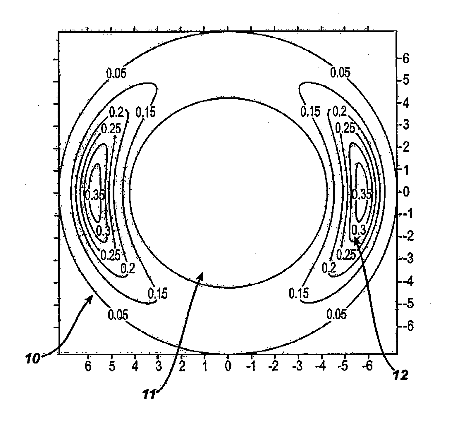
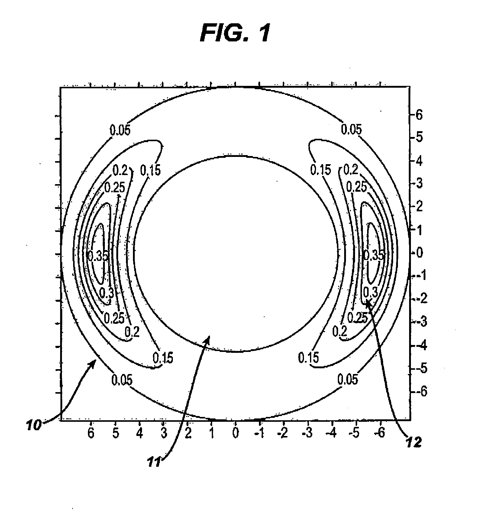
[0128]An improved stabilization design was obtained in which the final orientation of the stabilization zone was such that the peak location of the stabilization zone was changed angularly around the 0-180 deg. meridian from the geometrical center of the lens as shown in FIG. 6. Stabilization zones are no longer symmetric about the hor...
PUM
 Abstract
Description
Claims
Application Information