Method of detecting amount of axis displacement in power transmission device using automatic self-aligning engagement clutch

a technology of self-aligning and axis displacement, which is applied in the direction of interengaging clutches, couplings, instruments, etc., can solve the problems of difficulty in checking the amount of axis displacement during an operation, damage to the clutch, and the cost involved in the operation, etc., to achieve direct and accurate measurement of the amount of axis displacement, simple configuration, excellent cost and precision

Inactive Publication Date: 2011-06-23
MITSUBISHI HITACHIPOWER SYST LTD
View PDF7 Cites 23 Cited by
  • Summary
  • Abstract
  • Description
  • Claims
  • Application Information

AI Technical Summary

Benefits of technology

This patent describes how to automatically align two parts that are moving together without causing any damage or misaligned connections. It does this by measuring the distance they move while engaged with each other. By doing this, it can determine if there is any axial offset (when one part moves more than another) and quickly fix the problem before further damaging the system. Compared to existing methods that use multiple sensors and have higher costs and potential errors, this new approach provides better accuracy at lower cost.

Problems solved by technology

The technical problem addressed in this patent is how to accurately detect the movement of the axis in a power transmission system that uses an automatic self-aligning engagement clutch without requiring expensive and complex equipment. This allows for better control over the engagement process and reduces damage to the clutch from excessive stress caused by misaligned components.

Method used


Image

  • Method of detecting amount of axis displacement in power transmission device using automatic self-aligning engagement clutch
  • Method of detecting amount of axis displacement in power transmission device using automatic self-aligning engagement clutch
  • Method of detecting amount of axis displacement in power transmission device using automatic self-aligning engagement clutch

Examples


first embodiment

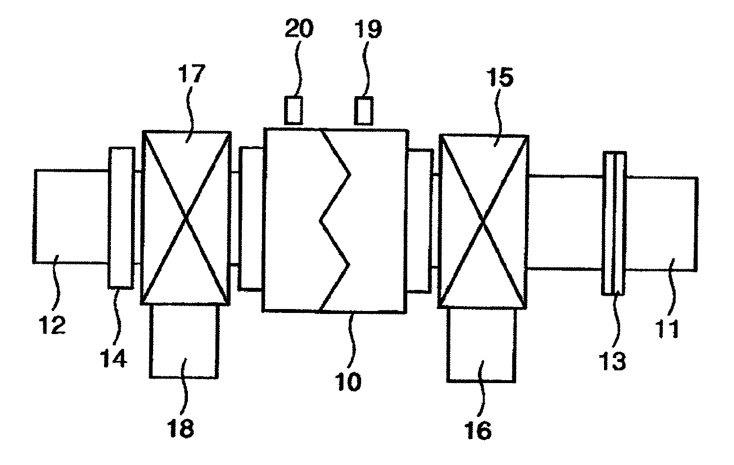
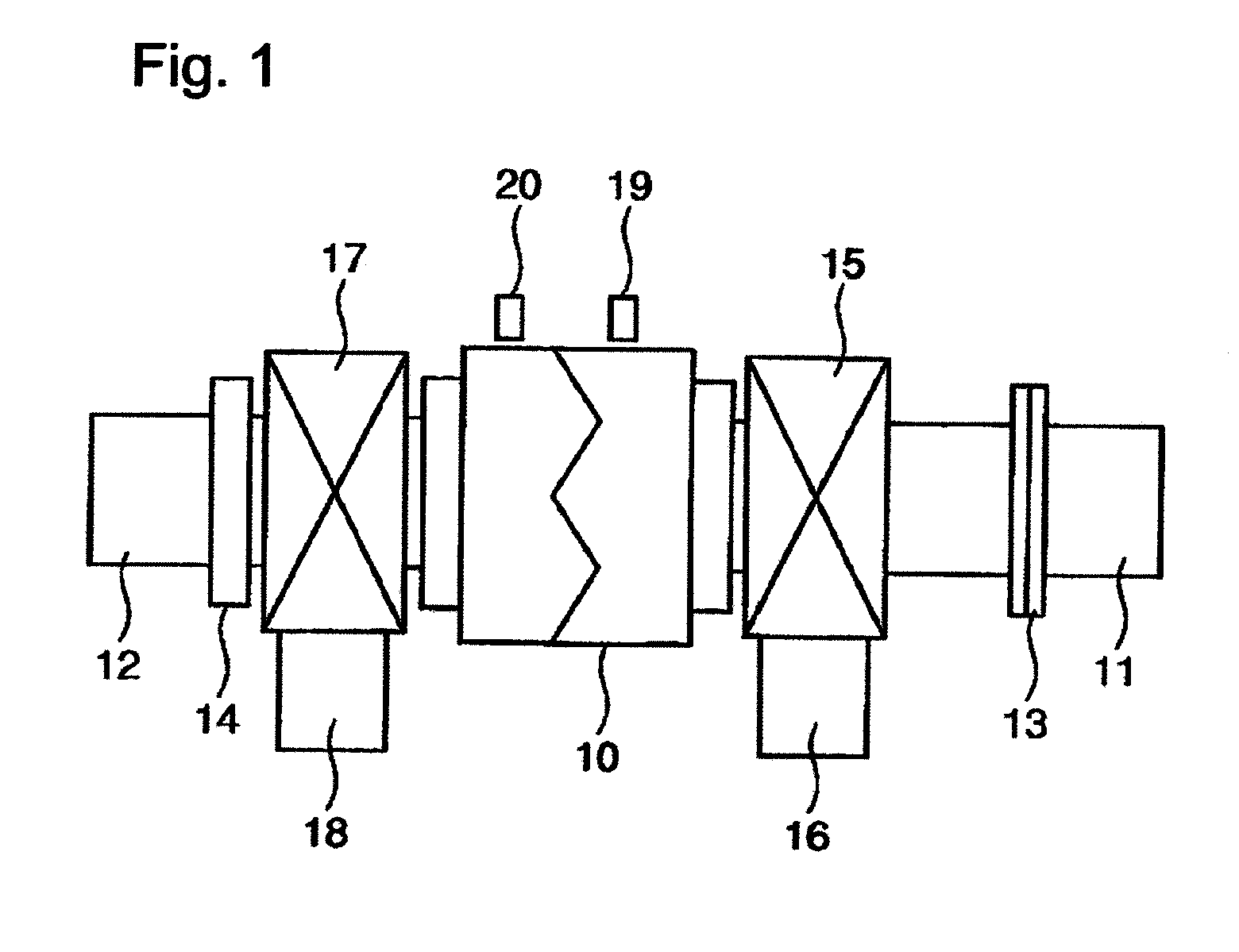
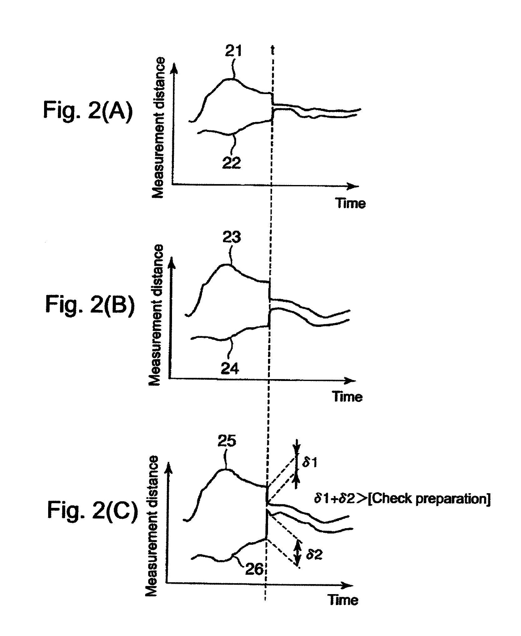
[0022]FIG. 1 is a block diagram showing a schematic example of a power transmission device and an arrangement state of proximity sensors for detecting an amount of an axis displacement, which are used to realize a method of detecting an amount of an axis displacement in a power transmission device using an automatic self-aligning engagement clutch according to the invention. FIG. 2(A) to 2(c) are graphs showing an example of an amount of an axis displacement due to a variation in age, where FIG. 2(A) shows a case immediately after an adjustment of an amount of an axis displacement, FIG. 2(B) shows a case after several years, and FIG. 2(C) shows a case after five years or more. FIG. 3 is a block diagram showing a configuration of an electric power facility as a single shaft combined plant which realizes a method of detecting an amount of an axis displacement in a power transmission device using an automatic self-aligning engagement clutch according to the invention.

[0023]First, the b...


PUM


Abstract

An object is to provide a method of detecting an amount of an axis displacement in a power transmission device using an automatic self-aligning engagement clutch, the method being capable of accurately detecting the amount of the axis displacement in the automatic self-aligning engagement clutch during an operation with a simple configuration. In a power transmission device configured to transmit a driving force to a driven body by allowing a rotary shaft of a first drive source to engage with a rotary shaft of a second drive source through an automatic self-aligning engagement clutch, an amount of an axis position variation of each of the rotary shaft of the first drive source and the rotary shaft of the second drive source are measured by non-contact sensors, and an amount of a relative axis displacement of the rotary shaft of the second drive source relative to the rotary shaft of the first drive source is detected on the basis of the measurement result of the amount of the axis position variation of each rotary shaft when the rotary shaft of the first drive source engages with the rotary shaft of the second drive source through the automatic self-aligning engagement clutch.

Description


Claims


Application Information

Patent Timeline
Owner MITSUBISHI HITACHIPOWER SYST LTD
Why Eureka
Try Eureka