Method for measuring flare amount, mask for measuring flare amount, and method for manufacturing device

a manufacturing device and flare amount technology, applied in the direction of photomechanical devices, instruments, printers, etc., can solve the problems of difficult to quantitatively inability to measure an amount of flare over the entire region, and inability to accurately measure an amount of flare, etc., to achieve accurate measurement of flare amount, easy management of manufacturing, and simple process

Inactive Publication Date: 2007-06-28
FUJITSU SEMICON LTD
View PDF14 Cites 2 Cited by
  • Summary
  • Abstract
  • Description
  • Claims
  • Application Information

AI Technical Summary

Benefits of technology

[0023] Advantageously, a method for measuring an amount of flare and a mask used for measuring an amount of flare of the present invention can accurately measure an amount of flare in a simple process.
[0024] In particular, if a routine check is performed on an apparatus used for manufacturing a device by the method for manufacturing a device of the present invention, time to replace and clean optical parts, for example, can be properly determined with ease so that, advantageously, the apparatuses used in manufacturing can be easily managed. Further, replacement or cleaning of optical parts can avoid decline in evenness of dimensions beforehand, resulting in prohibited decline in device performance and in yield.

Problems solved by technology

As a result, it is difficult to quantitatively measure an amount of flare and the measured amount is not very accurate.
Limitation to a position of a shading section makes it impossible to measure an amount of flare over the entire region.
In other words, Kirk cannot measure an amount of flare that reaches a region other than a shading section that has been set on a predetermined position.

Method used


Image

  • Method for measuring flare amount, mask for measuring flare amount, and method for manufacturing device
  • Method for measuring flare amount, mask for measuring flare amount, and method for manufacturing device
  • Method for measuring flare amount, mask for measuring flare amount, and method for manufacturing device

Examples


first embodiment

(a) First Embodiment

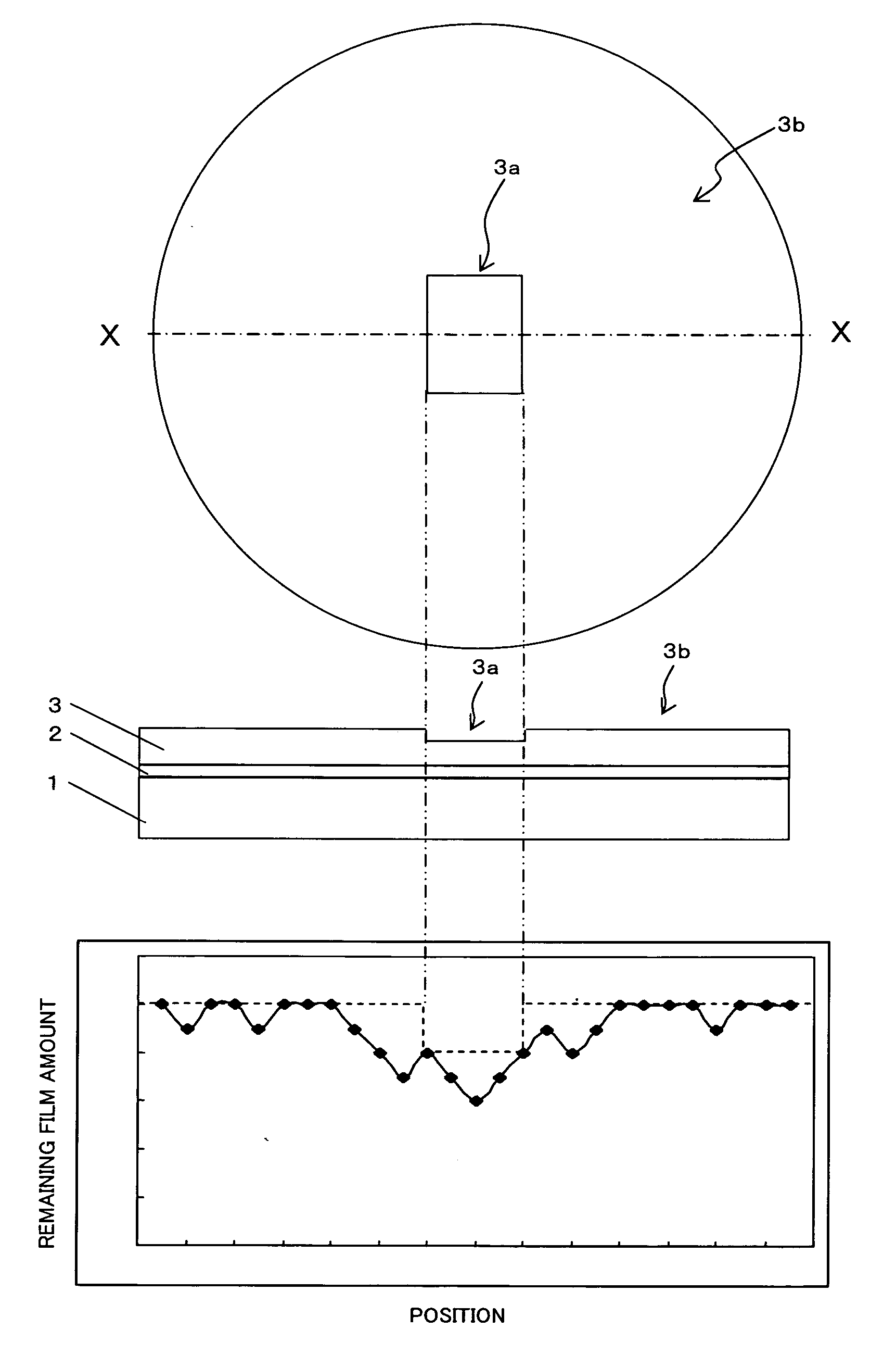
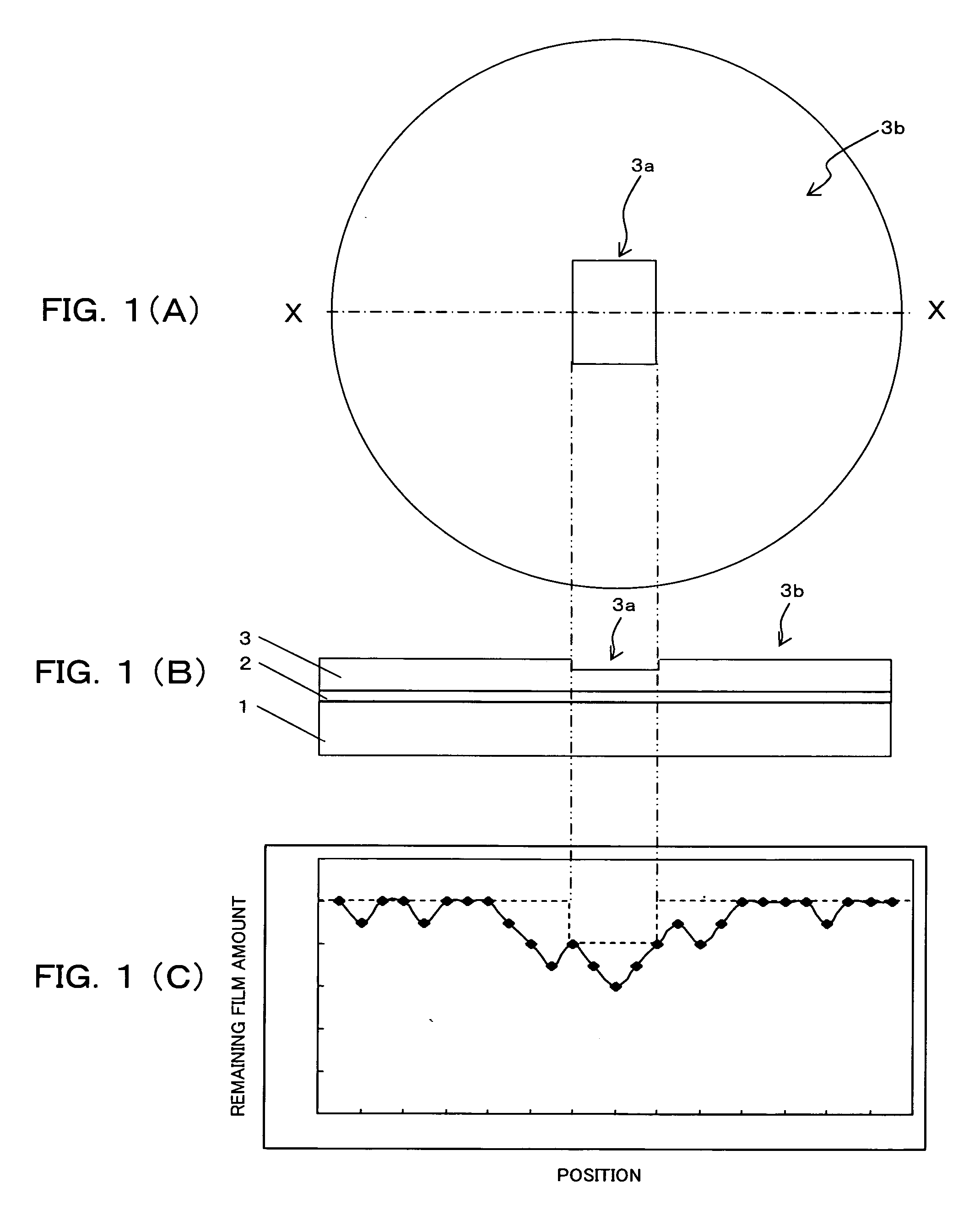
[0037] A method for measuring an amount of flare, a mask for measuring an amount of flare, and a method for manufacturing a device according to the first embodiment will now be described with reference to FIGS. 1(A)-1(C), 2(A), 2(B), 3 and 4.

[0038] A method for measuring an amount of flare according to the present embodiment is used in, for example, measurement of a flare amount caused by exposure in lithography when manufacturing semiconductor devices or display devices such as liquid crystal displays.

[0039] In the present invention, a flare amount is measured in the following manner

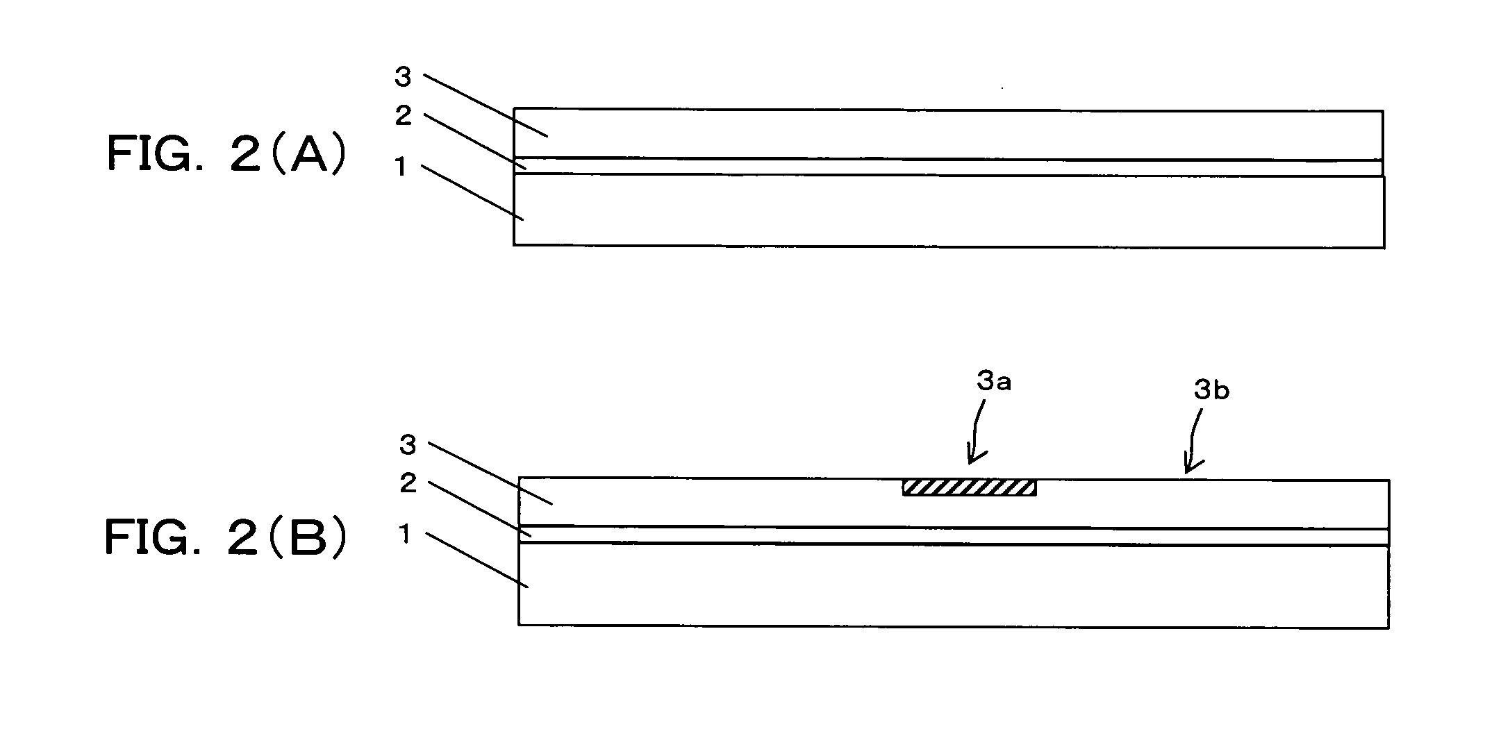
[0040] First of all, a resist 3 (a photosensitive material, a photoresist,) is applied to a wafer 1 (a semiconductor substrate, an Si substrate, here) interposed by a BARC (Bottom Anti-Reflection Coating) 2.

[0041] Then, a part of the resist 3 is exposed to light using a mask 4 (for measuring a flare amount, reticle) shown in FIG. 3 so that a part of the resist varies in thickness...

second embodiment

(b) Second Embodiment

[0066] A method for measuring an amount of flare, a mask used for measuring an amount of flare, and a method for manufacturing a device according to the second embodiment will now be described with reference to FIGS. 5 and 6.

[0067] A mask used for measuring an amount of flare according to the second embodiment is, as shown in FIG. 5, different in mask pattern from that used in the first embodiment (see FIG. 3).

[0068] Specifically, the mask 4A (a mask used for measuring an amount of flare, a reticle) has a number of line patterns which have different pitches (Pitch 1, Pitch 2, Pitch 3, . . . . Pitch n) at which lines are arranged, as shown in FIG. 5. These line patterns 4Aa are extending in a direction perpendicular to the scanning direction, being arranged in series in the scanning direction. The reference number 4Ab in FIG. 5 represents a shading section.

[0069] In the illustrated example, each line pattern 4Aa has a number of lines extending in a scanning di...

third embodiment

(c) Third Embodiment

[0081] A method for measuring an amount of flare, a mask used for measuring an amount of flare, and a method for manufacturing a device according to the third embodiment will now be described with reference to FIGS. 8-10.

[0082] As shown in FIG. 8, a method for measuring an amount of flare, a mask used for measuring an amount of flare, and a method for manufacturing a device of the present embodiment are different in mask pattern and in lighting system from the above first embodiment (see FIG. 3).

[0083] In the present embodiment, a mask (a mask used in measuring of an amount of flare, a reticle) 4C has, as shown in FIG. 8, a number of (here, two) line patterns 4Ca and 4Cb in blocks which are arranged at different angles relative to the scanning direction and in which lines are arranged in equal pitches. In FIG. 8, reference number 4 Cc represents a shading section.

[0084] In this example, one line pattern (first line pattern) 4Ca has a number of lines that exten...


PUM

PropertyMeasurementUnit
photosensitiveaaaaaaaaaa
thicknessaaaaaaaaaa
dimensionsaaaaaaaaaa

Abstract

An amount is flare is measured by a method including steps of applying a photosensitive material to a substrate; exposing a part of the photosensitive material using a mask including a transmitting section which has no pattern so that the part of the photosensitive material varies in thickness; and measuring an amount of flare based on a distribution of film amounts of the photosensitive material remaining in a first region corresponding to the transmitting section and on a second region other than the first region after the step of exposing.

Description

CROSS REFERENCE TO RELATED APPLICATIONS [0001] This application is based on and hereby claims priority to Japanese Application No. 2005-376024 filed on Dec. 27, 2005 in Japan, the contents of which are hereby incorporated by reference. BACKGROUND OF THE INVENTION [0002] 1. Field of the Invention [0003] The present invention relates to a method for measuring an amount of flare, a mask used for measuring an amount of flare, and a method for manufacturing a device which are preferably used in lithography using a photoresist (a photosensitive material) to form a pattern. [0004] 2. Description of the Related Art [0005] In accordance with recent high integration of semiconductor elements, patterns formed by lithographical methods have become finer and finer. [0006] Such finer design requires a smaller range for evenness of dimensions. [0007] Some reasons for worsening dimension evenness are flare (scattered or stray light) generated from a projection optical system and an illumination sys...

Claims


Application Information

Patent Timeline
Patent Type & Authority Applications(United States)
IPC IPC(8): G03B27/68G03F1/44G03F1/68G03F7/20H01L21/027
CPCG03F1/14G03F7/70483G03F7/70941G03F1/44G03F1/70
Inventor YAMAMOTO, TOMOHIKO
Owner FUJITSU SEMICON LTD
Why Eureka
Try Eureka