Light emitting device and method for tracking object
a technology of light emitting device and tracking object, which is applied in the direction of line-of-sight transmission, electromagnetic radiation sensing, instruments, etc., can solve the problems of difficult in principle to track such a pattern, and the technology of tracking a pattern changing in a complicated manner on moving images is unknown
- Summary
- Abstract
- Description
- Claims
- Application Information
AI Technical Summary
Benefits of technology
Problems solved by technology
Method used
Image

Examples
embodiment 1
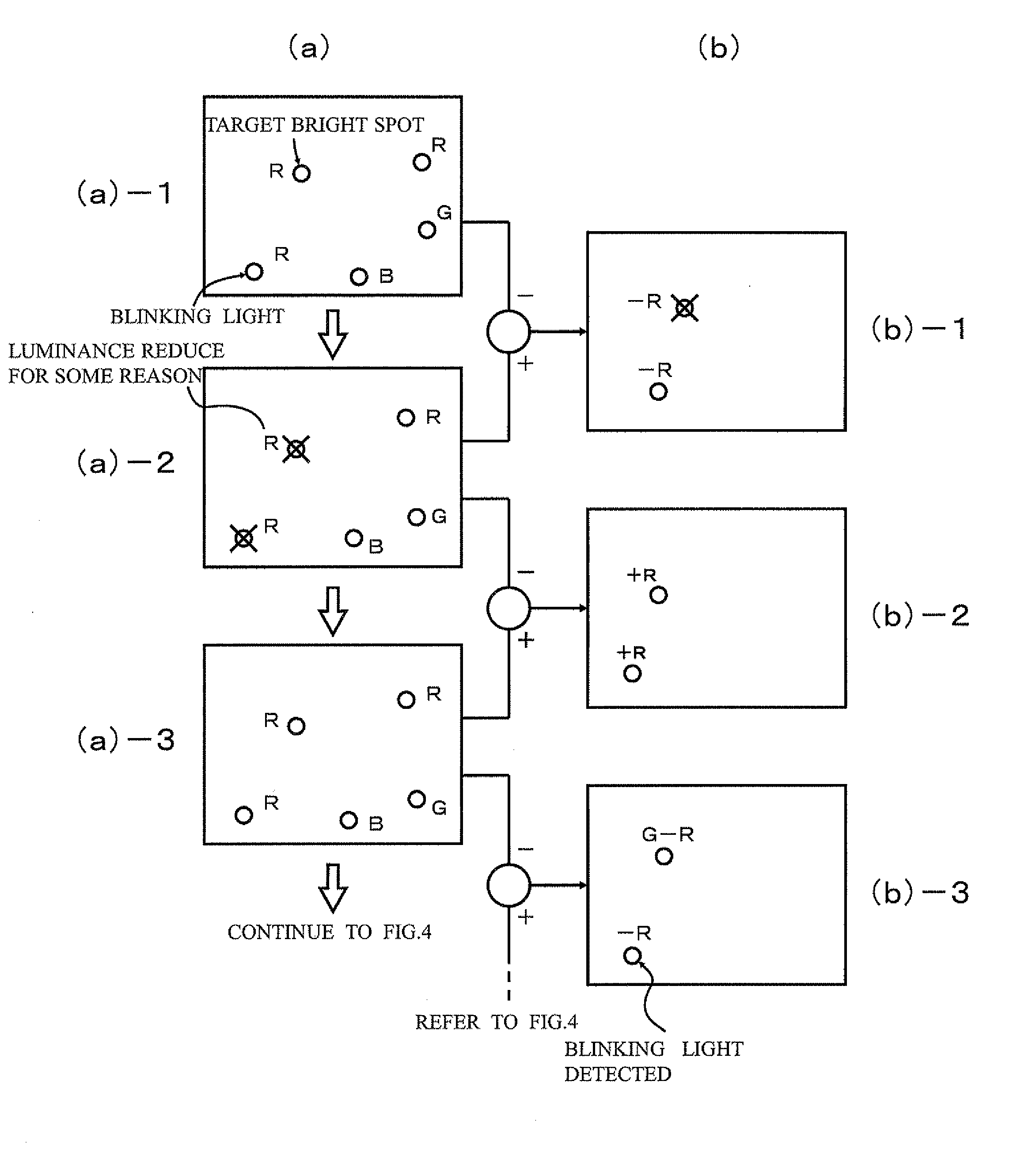
[0190]The principle of the present invention is to represent data by a “change” of a “color change” and most basic / preferable embodiments thereof are described with reference to the drawings.
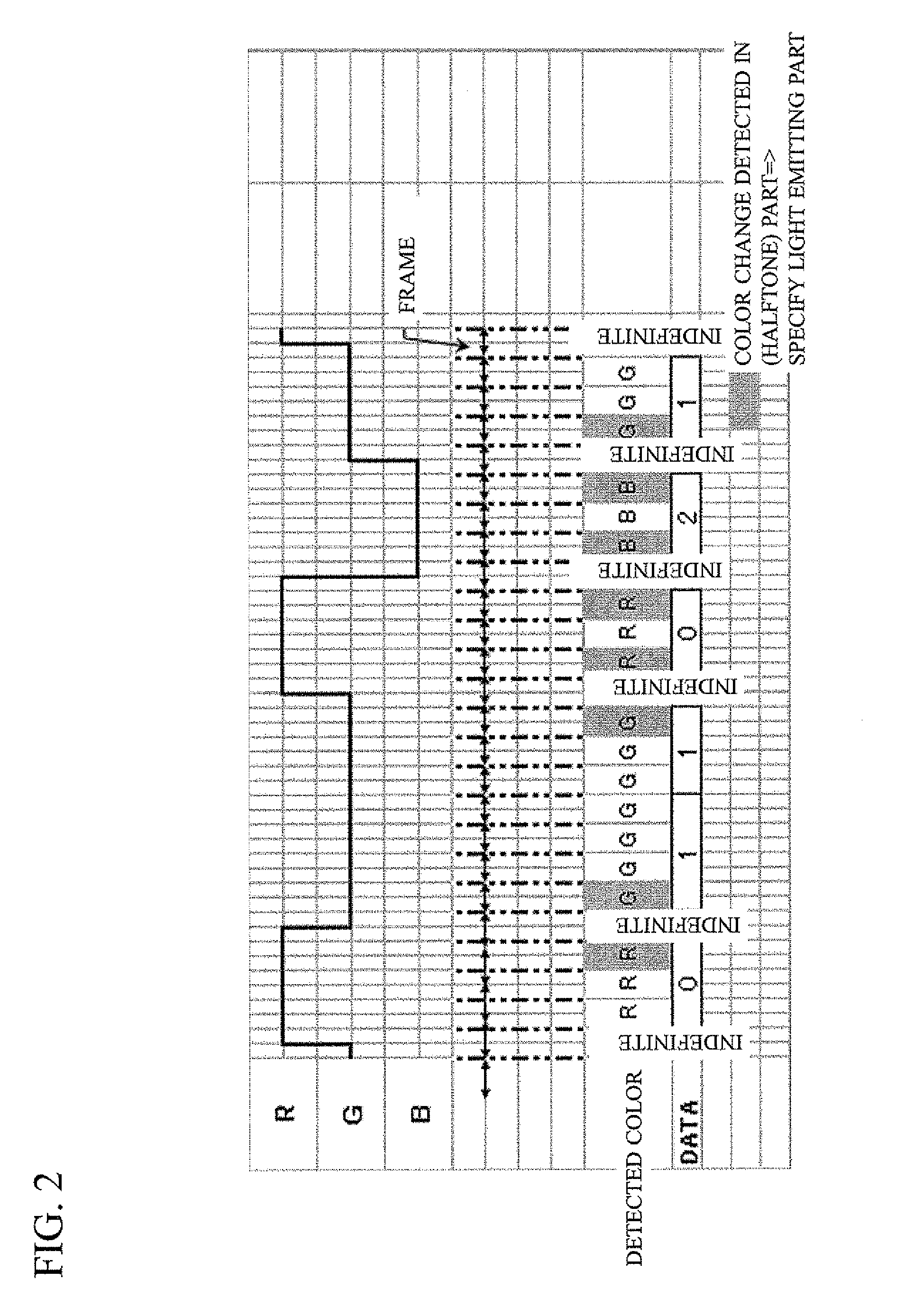
[0191]FIG. 9 shows a sequence diagram showing a light emission pattern in this embodiment. As shown in this sequence diagram, light of any one of RGB is emitted at one time in this embodiment similar to various technical plans described above. Sampling is performed at a time frame shown by chain double-dashed line in FIG. 9 to detect color. If the color does not change during the frame, the sampled color is uniquely determined. However, if sampling is performed at such a timing as to change the color during the frame, a sampling value becomes indefinite (see FIG. 9).
[0192]Values of data detected by sampling are shown in the bottommost row of FIG. 9.
[0193]As shown in FIG. 9, in this embodiment, data is allotted to each “change of a change” (a switch of a cyclic color change) as follows.
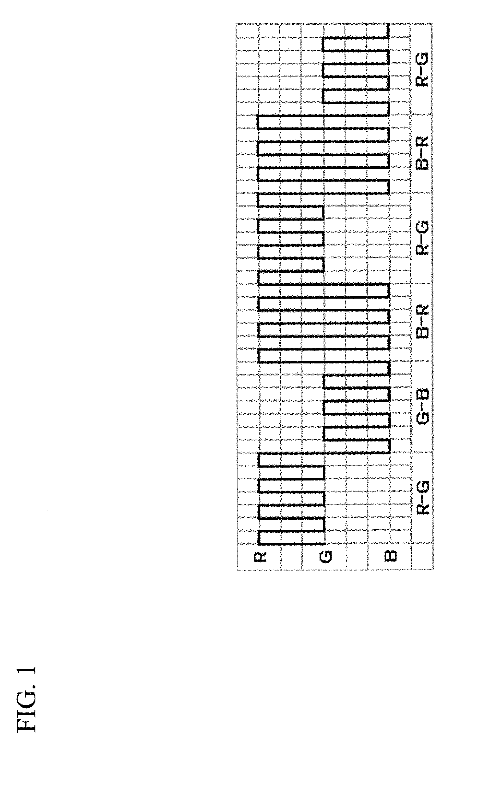
[0194]R*G→...
embodiment 2
; Plural Light Emitters
[0235]In the embodiment 1 is described the example where 1-bit data is recorded every time the color change is switched. Accordingly, let us study a switch of a color change, for example, under the following conditions.
[0236]Frame rate of a CCD camera used is 30 fps
[0237]Color changes every 1 / 15 sec.
[0238]Every time this color change occurs three times, this “color change” is switched.
* Note that the switch of the “color change” means a change of a combination of colors used for this “color change”. For example, a change from R*G to B*G is the switch of the “color change” mentioned here.
[0239]However, in principle, not only a change in color, but also a change in timing is treated as a switch of a color change. For example, a color change G→R→G→R at the same timing as a color change R→G→R→G or the like can be treated as a different color change, i.e. a switch of a color change. Such examples are described in detail later.
[0240]As mentioned before, a state wher...
embodiment 3
[0328]As described thus far, it has become possible to track an object and read displayed data by using switches of color changes.
[0329]A more specific data representation method is considered below.
[0330]First, regularity of making light emission patterns coherent data is considered. It is possible to display certain data by the technique described above. However, such a display of data is merely a list of data and it is necessary to clarify delimiters in order for this list of data to make sense.
[0331]Further, considering the characteristic of the present invention and the characteristic of the proposed light emission patterns, the presence of “ID data” indicating what is a light emitter (light emitting device) is generally necessary.
[0332]Further, considering the amount and rate of data that can be transmitted by this method, at is possible to superimpose (add) certain “transmission information” on (to) the “ID data”, which is meaningful for use in many cases. For example, the na...
PUM
 Abstract
Description
Claims
Application Information
 - R&D
- Intellectual Property
- Life Sciences
- Materials
- Tech Scout
- Unparalleled Data Quality
- Higher Quality Content
- 60% Fewer Hallucinations
Browse by: Latest US Patents, China's latest patents, Technical Efficacy Thesaurus, Application Domain, Technology Topic, Popular Technical Reports.
© 2025 PatSnap. All rights reserved.Legal|Privacy policy|Modern Slavery Act Transparency Statement|Sitemap|About US| Contact US: help@patsnap.com