
Reducing implementation costs of communicating cache invalidation information in a multicore processor

a multi-core processor and cache technology, applied in the field of processors, can solve the problems of increasing processor implementation costs, data to be invalidated may differ, etc., and achieve the effect of reducing the implementation cost of communicating cache invalidation information

Active Publication Date: 2011-06-23
ORACLE INT CORP
View PDF15 Cites 15 Cited by
  • Summary
  • Abstract
  • Description
  • Claims
  • Application Information

AI Technical Summary

Benefits of technology

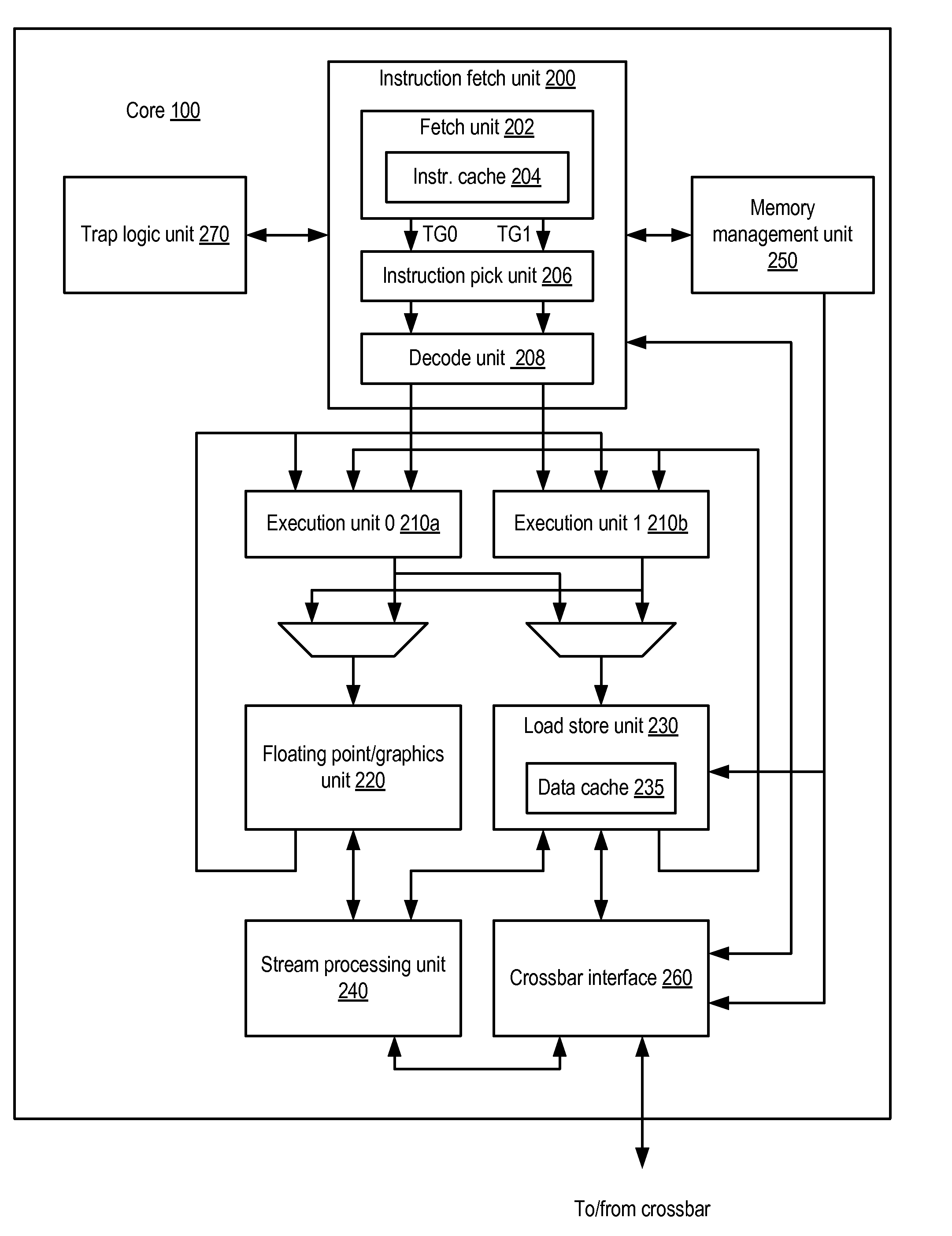
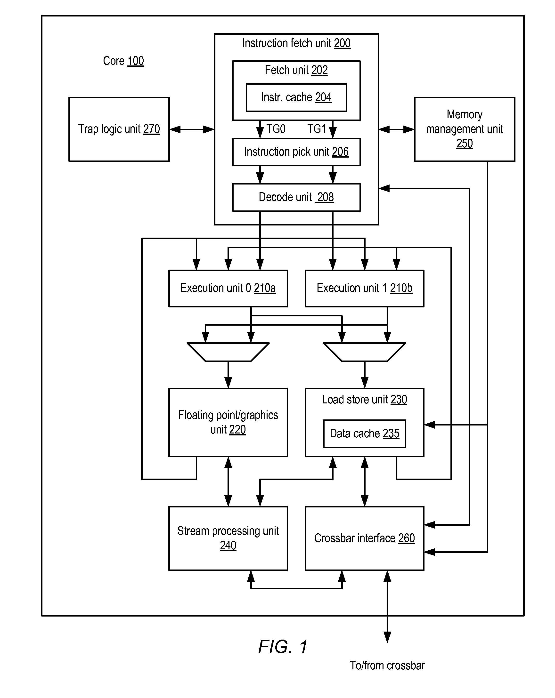
[0007]Various embodiments of techniques for reducing the implementation costs of communicating cache invalidation information in a multicore processor are disclosed. In some embodiments, a processor may include several processor cores, each including a respective higher-level cache, where each higher-level cache includes higher-level cache lines. The processor may also include a lower-level cache including lower-level cache lines, where each of the lower-level cache lines may be configured to store data that corresponds to multiple higher-level cache lines. In response to invalidating a given lower-level cache

Problems solved by technology

Depending on the configuration of the caches, certain memory activity that occurs with respect to the L2 cache may necessitate invalidation of data in each of the L1 caches.
However, the state of the data to be invalidated may differ among the various L1 caches.
As the number of cores increases, however, the complexity of routing an increased amount of invalidation information between the lower-level cache and the cores may increase processor implementation costs, in terms of factors such as die area and power consumption.

Method used


Image

  • Reducing implementation costs of communicating cache invalidation information in a multicore processor
  • Reducing implementation costs of communicating cache invalidation information in a multicore processor
  • Reducing implementation costs of communicating cache invalidation information in a multicore processor

Examples


example system embodiment

[0101]As described above, in some embodiments processor 10 as shown in FIG. 3 or 4 may be configured to interface with a number of external devices. An embodiment of a system including processor 10 is illustrated in FIG. 12. In the illustrated embodiment, system 1200 includes an instance of processor 10 coupled to a system memory 1210, a peripheral storage device 1220 and a boot device 1230. System 1200 is coupled to a network 1240, which is in turn coupled to another computer system 1250. In some embodiments, system 1200 may include more than one instance of the devices shown, such as more than one processor 10, for example. In various embodiments, system 1200 may be configured as a rack-mountable server system, a standalone system, or in any other suitable form factor. In some embodiments, system 1200 may be configured as a client system rather than a server system.

[0102]In various embodiments, system memory 1210 may comprise any suitable type of system memory as described above, ...


PUM


Abstract

A processor may include several processor cores, each including a respective higher-level cache, wherein each higher-level cache includes higher-level cache lines; and a lower-level cache including lower-level cache lines, where each of the lower-level cache lines may be configured to store data that corresponds to multiple higher-level cache lines. In response to invalidating a given lower-level cache line, the lower-level cache may be configured to convey a sequence including several invalidation packets to the processor cores via an interface, where each member of the sequence of invalidation packets corresponds to a respective higher-level cache line to be invalidated, and where the interface is narrower than an interface capable of concurrently conveying all invalidation information corresponding to the given lower-level cache line. Each invalidation packet may include invalidation information indicative of a location of the respective higher-level cache line within different ones of the processor cores.

Description

BACKGROUND[0001]1. Field of the Invention[0002]This invention relates to processors and, more particularly, to implementation of cache memory systems.[0003]2. Description of the Related Art[0004]To improve execution performance, processors commonly include multiple levels of caches. For example, a processor may include a fast first-level (L1) cache backed by a larger, slower second-level (L2) cache. Such an arrangement may reduce average memory access latency relative to an implementation in which the L2 cache is omitted, in that an L1 cache miss that hits in the L2 cache need not incur the full latency of an access to system memory.[0005]The integration of multiple processor cores into a single processor has resulted in configurations in which several independent L1 caches within the cores may share a common L2 cache. Depending on the configuration of the caches, certain memory activity that occurs with respect to the L2 cache may necessitate invalidation of data in each of the L1 ...

Claims


Application Information

Patent Timeline
IPC IPC(8): G06F12/08G06F12/00
CPCY02B60/1225G06F12/0897Y02D10/00
Inventor JAIN, PRASHANTDAS, SANDIPPATEL, SANJAY
Owner ORACLE INT CORP
Learn More