Evaporator with cool storage function

Inactive Publication Date: 2011-06-30
KEIHIN THERMAL TECH CORP
View PDF14 Cites 38 Cited by
  • Summary
  • Abstract
  • Description
  • Claims
  • Application Information

AI Technical Summary

Benefits of technology

[0022]According to the evaporator with a cool storage function of par. 1) to 9), each of the cool storage material containers includes a container body in thermal contact with the refrigerant flow tubes, and an internal-volume-increasing portion which extends from the container body toward the upstream side or downstream side with respect to the air flow direction, which projects outward, with respect to the air flow direction, from the refrigerant flow tube, and which is greater in dimension in a thickness direction than the container body. Therefore, the amount of the cool storage material charged into the cool storage material containers can be increased without increasing the lengths of the refrigerant flow tubes and the cool storage material containers, or increasing the container height (the dimension in the thickness direction) of the cool storage material containers over the entirety thereof, as in the evaporator with a cool storage function described in Japanese Patent No. 4043776. Accordingly, the size and weight of the evaporator can be reduced, as compared with the evaporator with a cool storage function described in Japanese Patent No. 4043776 in which the container height of the cool storage material containers is constant over the entirety thereof. Moreover, the time required to cool the cool storage material can be shortened as compared with the case where the container height is increased in the evaporator with a cool storage function described in Japanese Patent No. 4043776 in which the container height of the cool storage material containers is constant over the entirety thereof. Therefore, a drop in the cooling performance at the start of cooling operation is suppressed. In addition, since an inner fin extending from the container body to the internal-volume-increasing portion is disposed in each cool storage material container, the cool storage material within the internal-volume-increasing portion is cooled quickly. Accordingly, the cool storage material within the cool storage material containers can be cooled efficiently.
[0023]Furthermore, the internal-volume-increasing portion extends from the container body toward the upstream side or downstream side with respect to the air flow direction and projects outward, with respect to the air flow direction, from the refrigerant flow tube. Therefore, even in the case where a plurality of assemblies each composed of a refrigerant flow tube and a cool storage material container whose container body is in thermal contact with the refrigerant flow tube are disposed at intervals in a direction perpendicular to the width direction of the refrigerant flow tubes, and spaces each formed between adjacent assemblies serve as air-passing clearances, the amount of the cool storage material charged into the cool storage material containers can be increased without changing the dimensions of the heat exchange core section. Accordingly, a decrease in the areas of the air-passing clearance can be suppressed as compared with the evaporator with a cool storage function described in Japanese Patent No. 4043776, w

Problems solved by technology

Incidentally, an ordinary car air conditioner has a problem in that, when an engine of an automobile in which the air conditioner is mounted is stopped, a compressor driven by the engine is stopped, and supply of refrigerant to an evaporator stops, whereby the cooling capacity of the air conditioner sharply drops.
However, when t

Method used


Image

  • Evaporator with cool storage function
  • Evaporator with cool storage function
  • Evaporator with cool storage function

Examples


Embodiment Construction

[0035]An embodiment of the present invention will next be described with reference to the drawings.

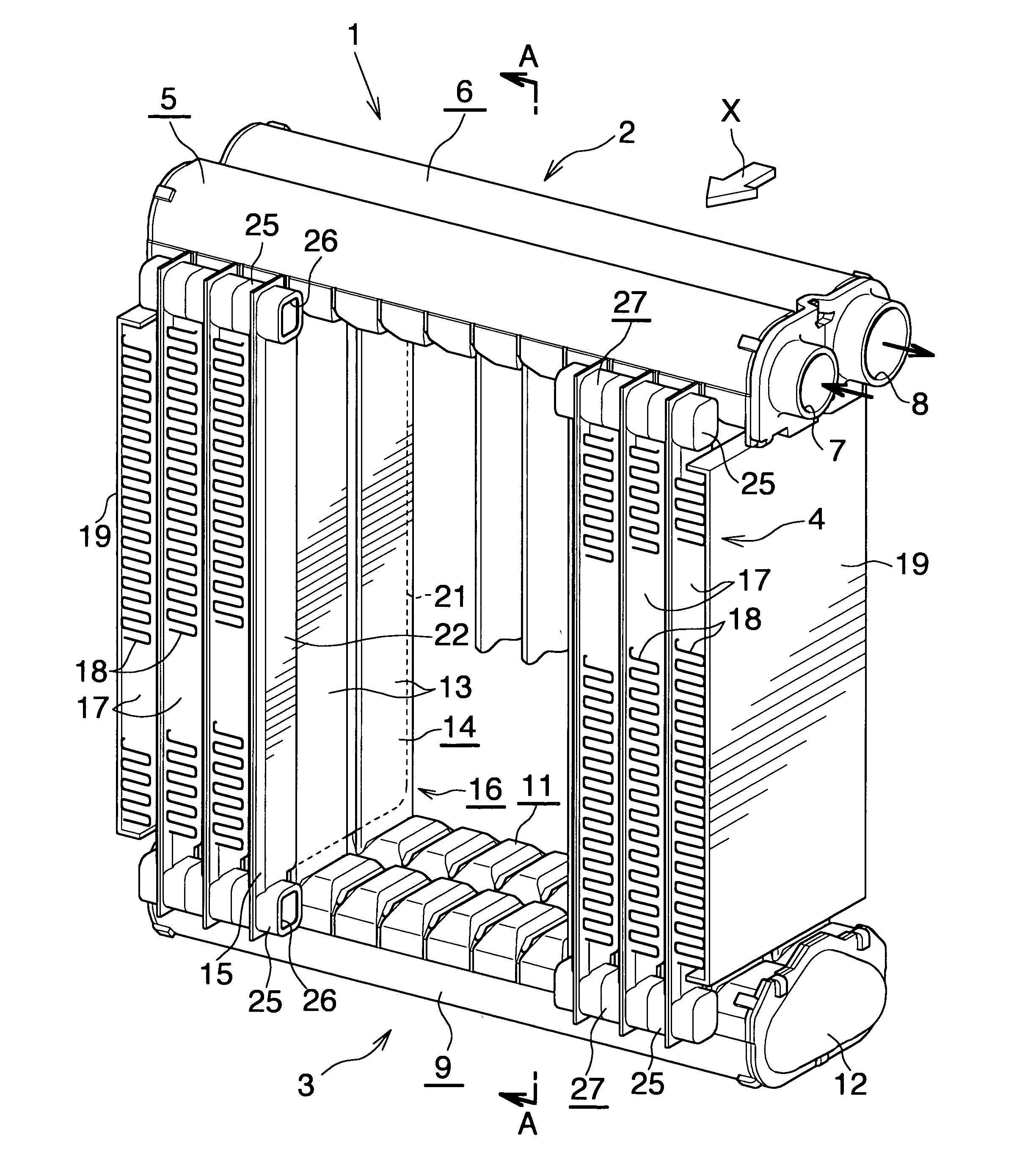
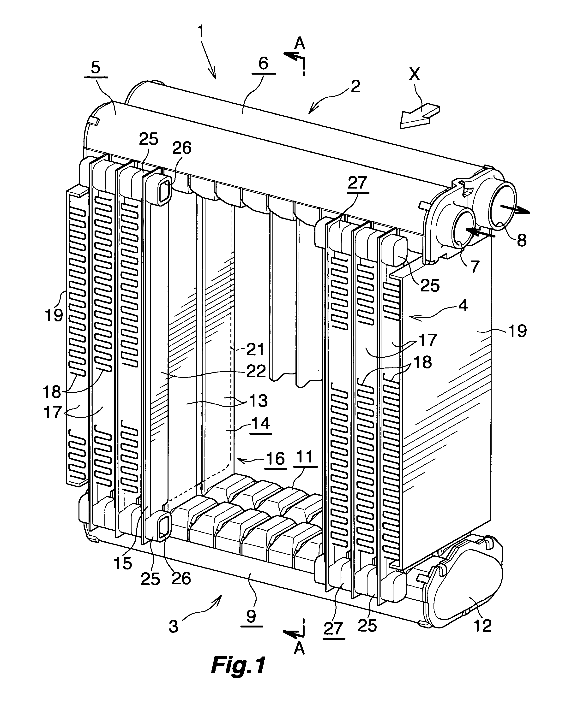
[0036]In the following description, the downstream side with respect to the air flow direction (a direction represented by arrow X in FIGS. 1 to 4) will be referred to as the “front,” and the opposite side as the “rear.” Further, the left-hand and right-hand sides as viewed rearward from the front side; i.e., the left-hand and right-hand sides of FIG. 1, will be referred to as “left” and “right,” respectively.

[0037]In the following description, the term “aluminum” encompasses aluminum alloys in addition to pure aluminum.

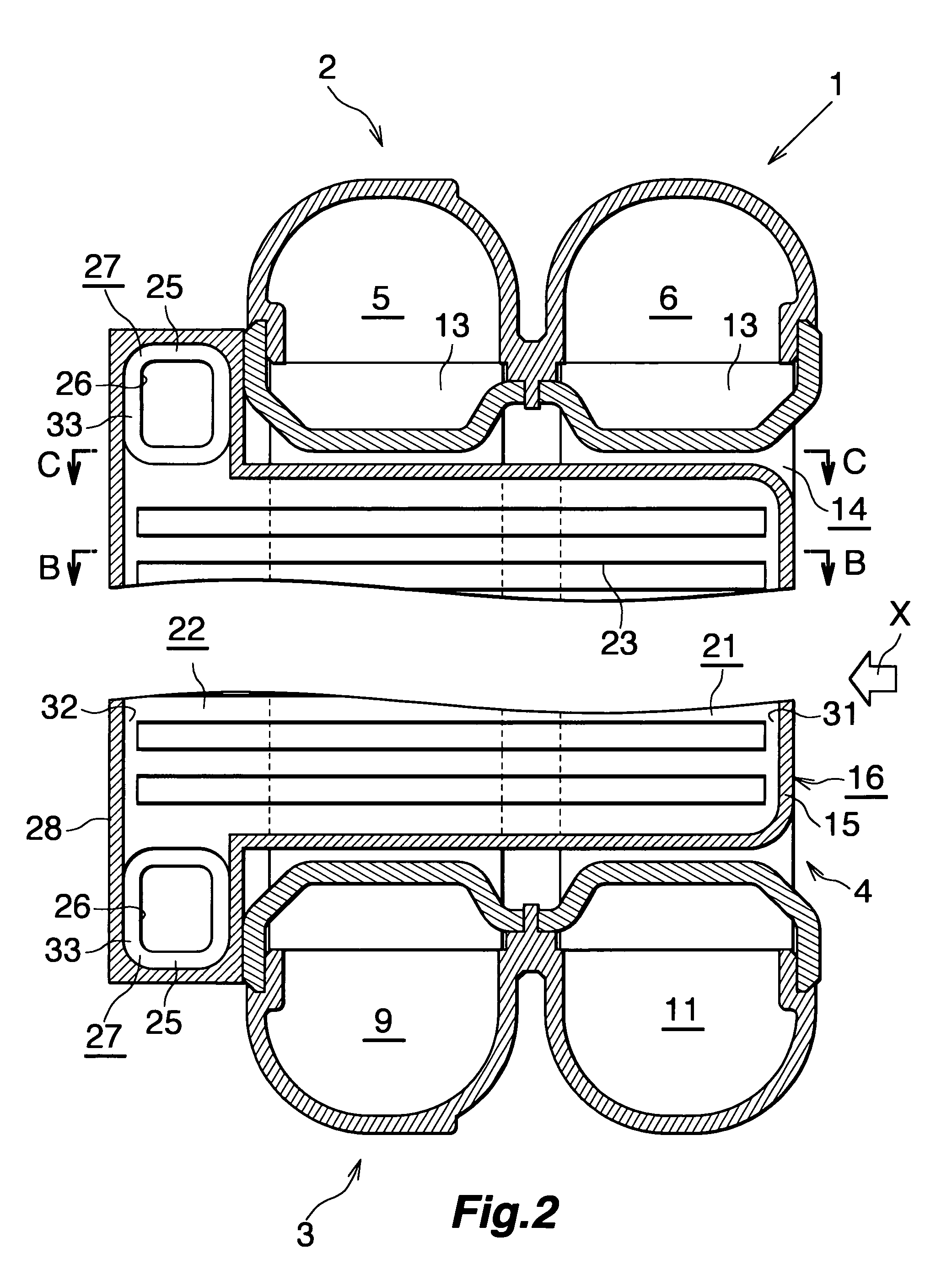
[0038]FIG. 1 shows the overall configuration of an evaporator with a cool storage function according to the present invention, and FIGS. 2 to 6 show the configurations of essential portions of the evaporator.

[0039]As shown in FIGS. 1 and 2, an evaporator with a cool storage function 1 includes a first header tank 2 and a second header tank 3 formed of aluminum and dispo...


PUM


Abstract

An evaporator with a cool storage function includes a plurality of flat refrigerant flow tubes spaced apart from one another, and a plurality of flat cool storage material containers each of which contains a cool storage material and is disposed on one side of the corresponding refrigerant flow tube, and is brazed to the corresponding refrigerant flow tube. The cool storage material container includes a container body brazed to the corresponding refrigerant flow tube, and an internal-volume-increasing portion which extends downstream from the container body, which projects downstream from the refrigerant flow tube, and which is greater in dimension in a thickness direction than the container body. An inner fin extending from the container body to the internal-volume-increasing portion is disposed in the cool storage material container. This evaporator is suitable for a refrigeration cycle which constitutes a car air conditioner.

Description

BACKGROUND OF THE INVENTION[0001]The present invention relates to an evaporator with a cool storage function for use in a car air conditioner for a vehicle in which an engine serving as a drive source for a compressor is temporarily stopped when the vehicle is stopped.[0002]Herein and in the appended claims, the upper side and lower side of FIGS. 1 and 2 will be referred to as “upper” and “lower,” respectively.[0003]In recent years, in order to protect the environment and improve fuel consumption of automobiles, there has been proposed an automobile designed to automatically stop the engine when the automobile stops, for example, so as to wait for a traffic light to change.[0004]Incidentally, an ordinary car air conditioner has a problem in that, when an engine of an automobile in which the air conditioner is mounted is stopped, a compressor driven by the engine is stopped, and supply of refrigerant to an evaporator stops, whereby the cooling capacity of the air conditioner sharply ...

Claims


Application Information

Patent Timeline
IPC IPC(8): F25B39/02F28F7/00
CPCF25B39/022F25B2400/24F28D1/05391F28D20/0034Y02E60/145F28D2020/0013F28D2021/0085F28F3/025Y02E60/142F28D20/02Y02E60/14
Inventor SASAKI, HIRONAKAHIGASHIYAMA, NAOHISAKAMOSHIDA, OSAMUTAKAGI, MOTOYUKI
Owner KEIHIN THERMAL TECH CORP
Why Eureka
Try Eureka