
Mask Pressure Regulation in Cpap Treatment and Assisted Respiration by Dynamic Control of Mask Vent Flow

a mask and pressure regulation technology, applied in the field of air delivery system, can solve the problems of increasing noise and bearing wear, fundamental limitations, and pressure swings at the mask, and achieve the effect of constant air flow

Active Publication Date: 2011-06-30
RESMED LTD
View PDF17 Cites 18 Cited by
  • Summary
  • Abstract
  • Description
  • Claims
  • Application Information

AI Technical Summary

Benefits of technology

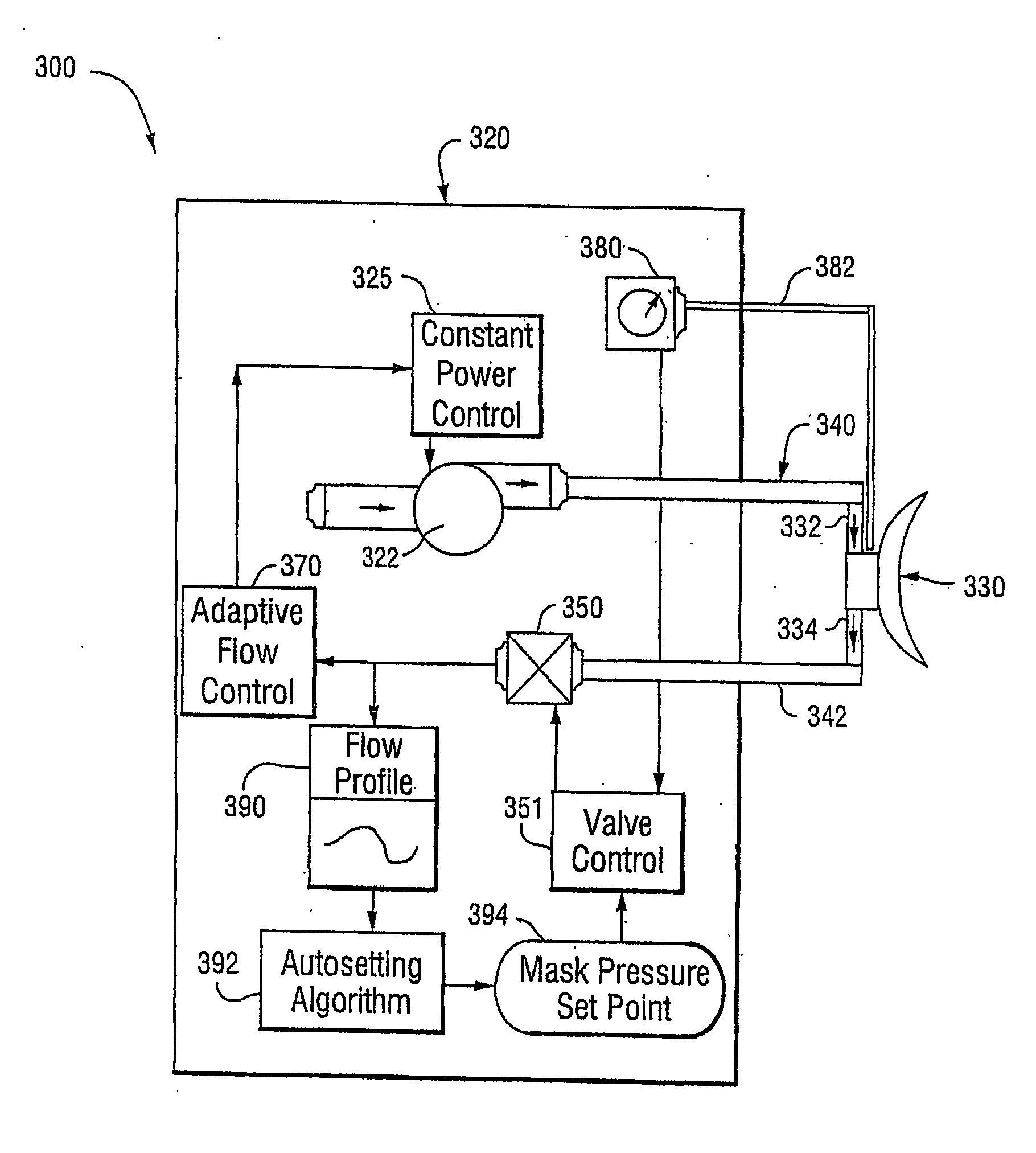
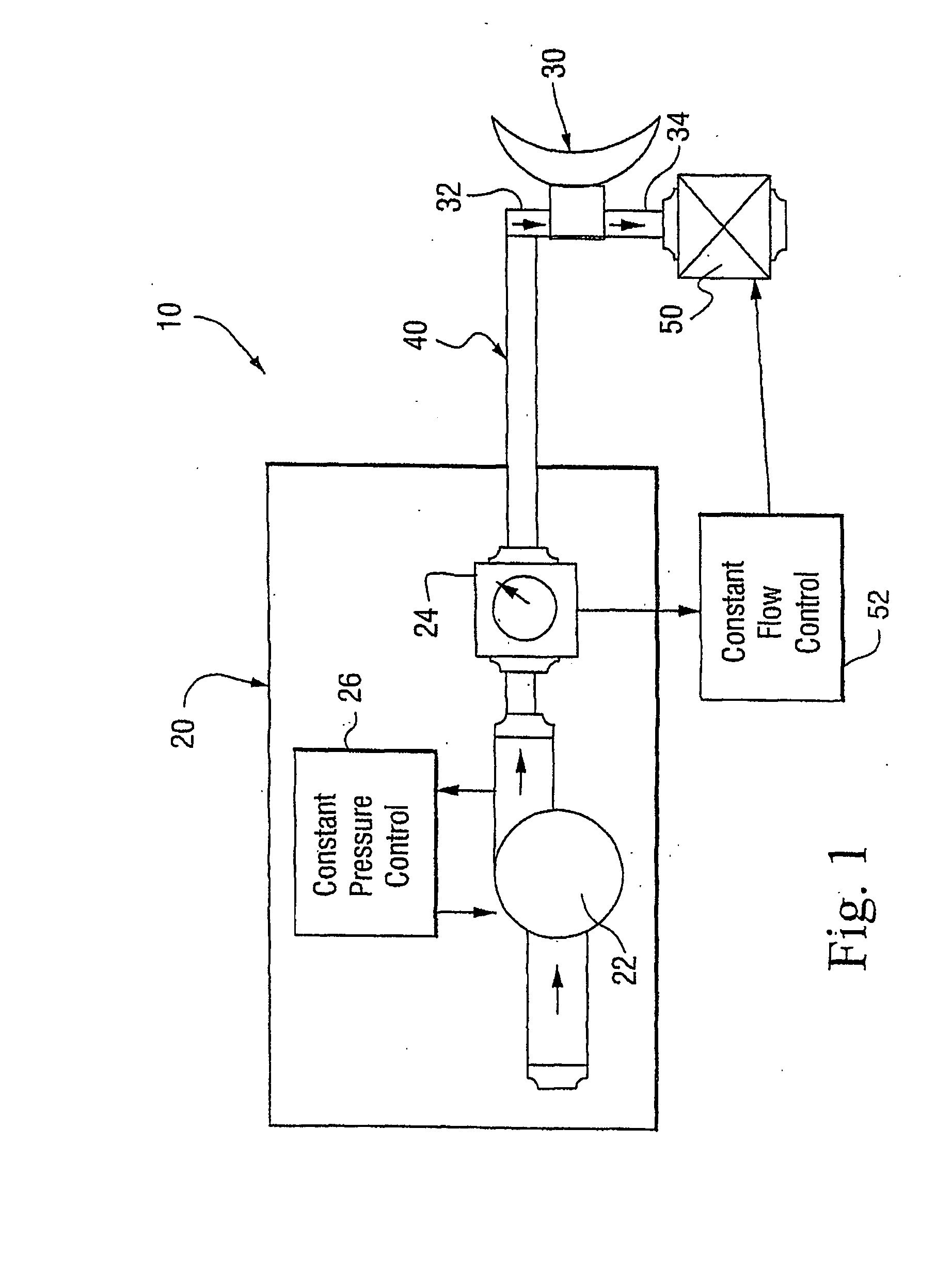
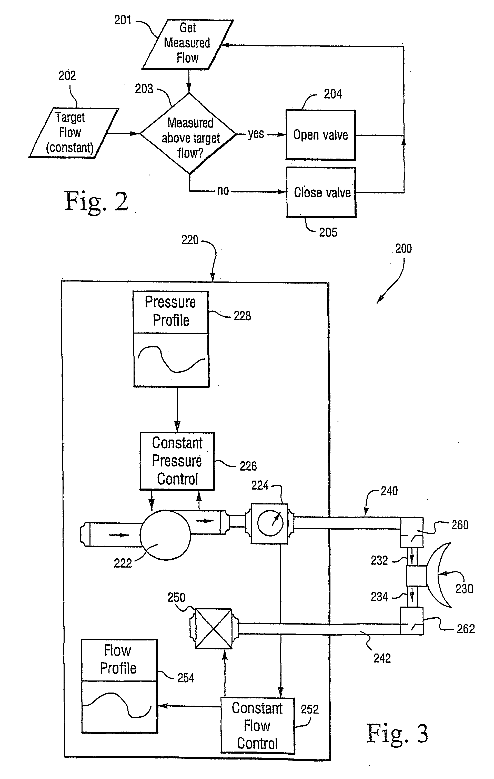
The invention relates to methods and systems for delivering pressurized air to a patient's airway during continuous positive airway pressure (CPAP) treatment or assisted respiration. The invention aims to compensate for pressure swings at the patient's airway caused by respiratory flow. The invention includes an air delivery system with a controllable vent valve to control venting from the patient interface and maintain a constant air flow in the air delivery conduit and the air flow generator. The method of delivering pressurized air to a patient involves delivering air to the patient interface and controlling venting from the patient interface to maintain a constant air flow or pressure at the patient interface. The technical effects of the invention include improved respiratory therapy and patient comfort during respiratory treatment.

Problems solved by technology

One problem with CPAP therapy is that the flow impedance of a flow generator air delivery path results in pressure swings at the mask when the breathing load changes.
However, compensating for the pressure swings by adjusting the turbine pressure results in increased noise and bearing wear, and is fundamentally limited by the rate at which the turbine pressure can be changed, e.g., see U.S. Pat. No. 6,332,463.
However, maintaining a low flow impedance of the delivery air path in a flow generator may compromise other product design goals, e.g., the turbine inlet air path being constrained to reduce radiated noise, the delivery hose being reduced in diameter, or a humidifier or filter being added to the patient circuit.
Under these conditions, it may be difficult to lower the pressure swings at the mask to clinically acceptable levels and therapy delivery may be compromised.

Method used


Image

  • Mask Pressure Regulation in Cpap Treatment and Assisted Respiration by Dynamic Control of Mask Vent Flow
  • Mask Pressure Regulation in Cpap Treatment and Assisted Respiration by Dynamic Control of Mask Vent Flow
  • Mask Pressure Regulation in Cpap Treatment and Assisted Respiration by Dynamic Control of Mask Vent Flow

Examples


Embodiment Construction

[0020]The air delivery methods or systems described below are alternatives to the methods described in U.S. Pat. No. 6,332,463 to ResMed Limited, the entirety incorporated herein by reference. In the illustrated embodiments described herein, the air delivery methods or systems eliminate the effect of delivery circuit impedance on mask pressure swings without requiring a dynamic adjustment of the turbine speed. Because the methods or systems described below are not restricted by the physical response of a mechanical rotating element (i.e., a valve has a faster response time), they potentially allow the use of more restrictive air paths.

[0021]Aspects of the air delivery methods or systems described below may be incorporated into other systems such as the Ventless Mask CPAP System described in U.S. Patent Application No. 60 / 706,430, filed Aug. 9, 2005, the entirety incorporated herein by reference.

1. First Illustrated Embodiment of Air Delivery System

[0022]FIG. 1 illustrates an air del...


PUM


Abstract

An air delivery system includes an air flow generator to provide a pressurized flow of air, a patient interface to provide a seal with the patient's face in use, an air delivery conduit to interconnect the air flow generator and the patient interface, and a controllable vent valve to control venting from the patient interface. The vent valve is controlled to maintain a substantially constant air flow in the air delivery conduit and the air flow generator.

Description

CROSS-REFERENCE TO APPLICATIONS[0001]This application claims the benefit of U.S. Provisional Application Nos. 60 / 667,052, filed Apr. 1, 2005, 60 / 706,430, filed Aug. 9, 2005, and 60 / 775,334, filed Feb. 22, 2006, each incorporated by reference in its entirety.FIELD OF THE INVENTION[0002]The present invention relates to an air delivery system used for treatment, e.g., of sleep disordered breathing (SDB) such as obstructive sleep apnea (OSA).BACKGROUND OF THE INVENTION[0003]Patients who suffer from obstructive sleep apnea can use continuous positive airway pressure (CPAP) therapy to maintain the upper airway open while they are asleep. CPAP therapy is applied to the patient using a mask, tubing, and a flow generator. All of these components encompass the air delivery system provided to the patient.[0004]One problem with CPAP therapy is that the flow impedance of a flow generator air delivery path results in pressure swings at the mask when the breathing load changes. As the impedance of...

Claims


Application Information

Patent Timeline
Patent Type & Authority Applications(United States)
IPC IPC(8): A61M16/20A61M16/06
CPCA61M16/00A61M16/0066A61M16/06A61M2016/0027A61M2016/0039A61M2206/14A61M16/22A61M16/0009A61M16/0633A61M16/0672A61M16/0883A61M16/202A61M2230/432A61M16/1055A61M16/0012A61M16/0093A61M16/1065A61M16/0825A61M16/0622A61M16/024
Inventor BARNES, ADRIANOATES, JOHN DAVIDKENYON, BARTON JOHNGOELDI, BENRIAH
Owner RESMED LTD
Learn More