

Liquid cooling device
- Summary
- Abstract
- Description
- Claims
- Application Information
AI Technical Summary
Benefits of technology
Problems solved by technology
Method used
Image

Examples
Embodiment Construction
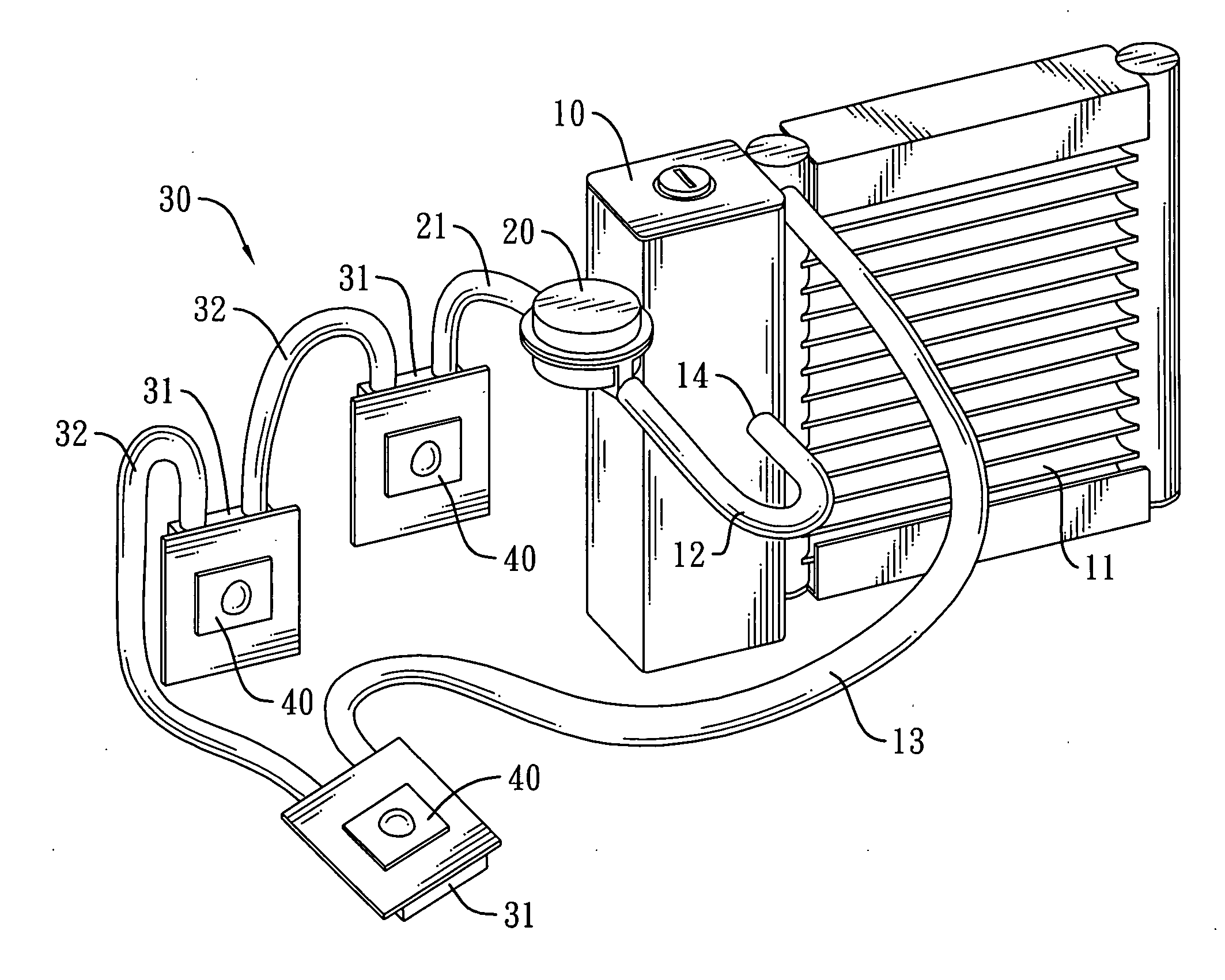
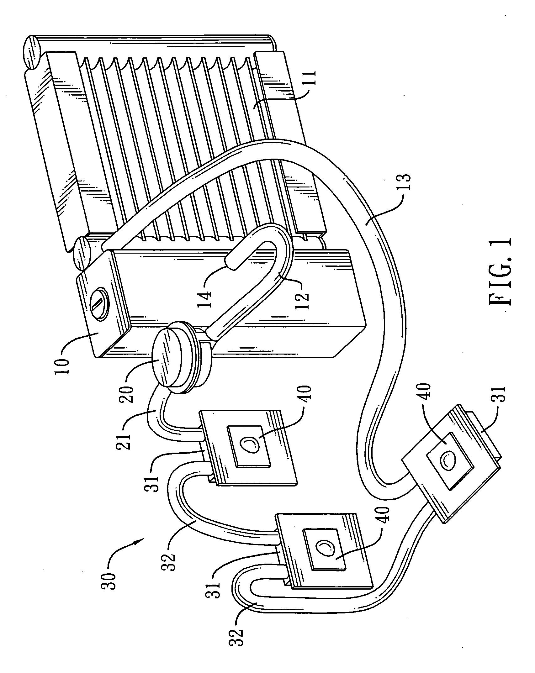
[0013]With reference to FIG. 1, a liquid cooling device in accordance with the present invention is mounted in a large-sized overhead projector to absorb heat generated by a light-generating device 40. The liquid cooling device is filled with a coolant and comprises a water tank 10, a heat sink 11, a liquid block assembly 30 and a pump 20.
[0014]The water tank 10 is hollow and has a top surface, a bottom surface, a middle, a side surface and an outlet hole 14. The outlet hole 14 is formed on the middle of the housing and communicates with the chamber. The distance between the outlet hole 14 and the top surface of the housing is almost equal to the distance between the outlet hole 14 and the bottom surface of the housing.
[0015]The heat sink 11 is connected with the side surface of the water tank 10.
[0016]The liquid block assembly 30 communicates with the heat sink 11 via an inlet duct 13. In this embodiment, the liquid block assembly 30 comprises multiple liquid blocks 31. The liquid ...
PUM
 Abstract
Description
Claims
Application Information