Vibratory actuator

a technology of vibrating actuator and actuator, which is applied in piezoelectric/electrostrictive/magnetostrictive devices, piezoelectric/electrostriction/magnetostriction machines, electrical equipment, etc., can solve the problems of easy chipping of edges and degradation of ultrasonic actuator reliability, and achieve the effect of improving the reliability of ultrasonic actuators

Inactive Publication Date: 2011-06-30
PANASONIC CORP
View PDF10 Cites 10 Cited by
  • Summary
  • Abstract
  • Description
  • Claims
  • Application Information

AI Technical Summary

Benefits of technology

[0008]According to the present disclosure, even if one connecting part between the external and side electrodes is damaged due to damage at the edge, the connection between the external and side electrodes can be maintained in another connecting part. Thus, the reliability of the ultrasonic actuator can be improved.

Problems solved by technology

However, such an edge is easily chipped off due to, e.g., an impact from outside.
The damageable electrodes result in degradation of reliability of an ultrasonic actuator.

Method used


Image

  • Vibratory actuator
  • Vibratory actuator
  • Vibratory actuator

Examples


Embodiment Construction

/ b>FIG. 11 is an exploded perspective view of an actuator body of a second variation.

[0020]FIG. 12 is a perspective view of the actuator body of the second variation.

[0021]FIG. 13 is an exploded perspective view of an actuator body of a third variation.

[0022]FIG. 14 is a perspective view of the actuator body of the third variation.

[0023]FIG. 15 is a perspective view of a drive unit of other embodiment.

[0024]FIG. 16 is a perspective view of a drive unit of another embodiment.

DETAILED DESCRIPTION

[0025]Example embodiments of the present disclosure will be described in detail below with reference to the drawings.

Embodiments of the Disclosure

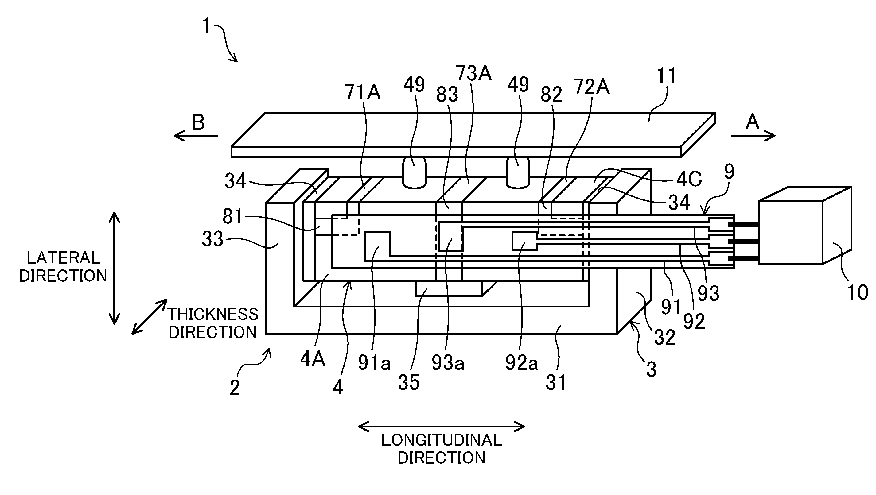
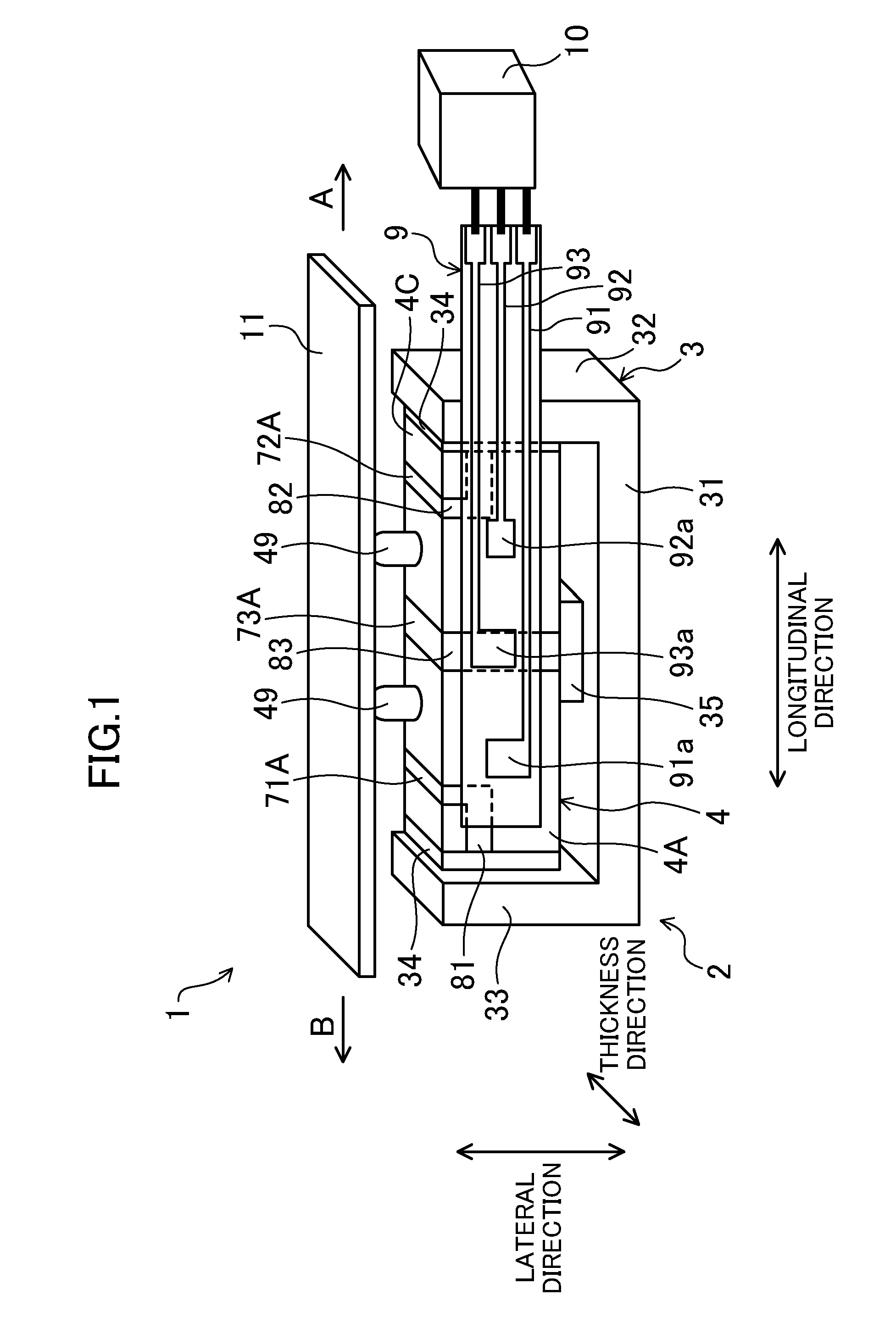
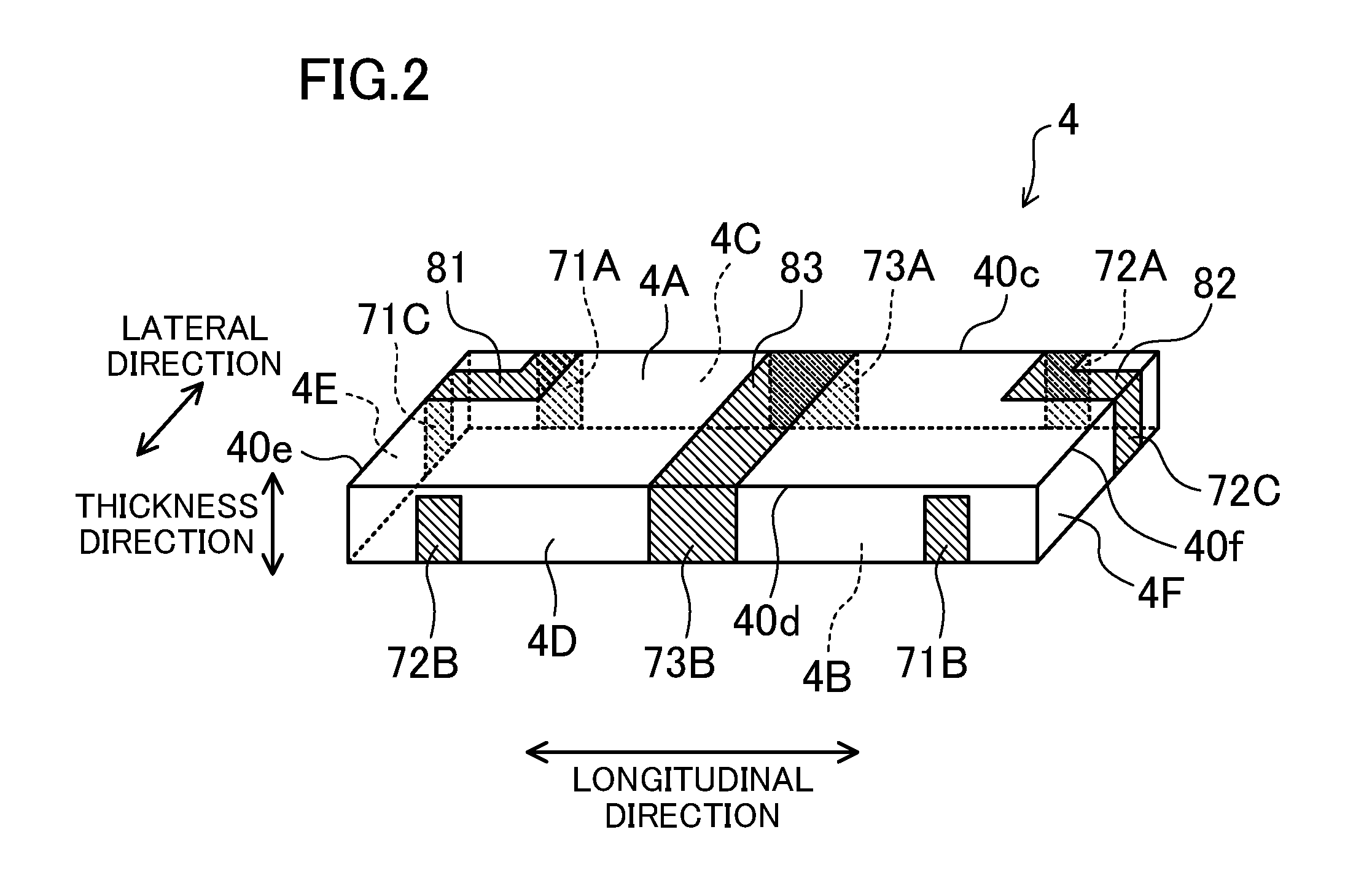
[0026]FIG. 1 is a view schematically illustrating a configuration of a drive unit 1 of an embodiment, and FIG. 2 is a perspective view of an actuator body 4. As illustrated in FIG. 1, the drive unit 1 includes a stage 11, an ultrasonic actuator 2, and a control unit 10 for controlling a drive of the ultrasonic actuator 2.

[0027]The stage 11 is slidabl...


PUM


Abstract

In an ultrasonic actuator, piezoelectric layers and internal electrode layers are stacked. External electrodes are formed on a principal surface exposed to an outside of the outermost piezoelectric layer. Side electrodes connected to the internal electrode layers and the external electrodes are formed on side surfaces of a body including the piezoelectric layers and the internal electrode layers. A first divided electrode and a first external electrode are connected together by a plurality of side electrodes. A second divided electrode and a second external electrode are connected together by a plurality of side electrodes. A minus electrode layer and a third external electrode are connected together by a plurality of side electrodes.

Description

CROSS-REFERENCE TO RELATED APPLICATION[0001]This application claims priority to Japanese Patent Application No. 2009-293784 filed on Dec. 25, 2009, the disclosure of which including the specification, the drawings, and the claims is hereby incorporated by reference in its entirety.BACKGROUND[0002]The present disclosure relates to a vibratory actuator in which a plurality of piezoelectric layers are stacked.[0003]Conventionally, a vibratory actuator has been known, which includes piezoelectric elements (electromechanical transducer elements), and which is used for various electric devices. Such a vibratory actuator includes a plurality of stacked piezoelectric layers; and internal electrodes, each of which is sandwiched between the piezoelectric layers. In the vibratory actuator, voltage is applied to the piezoelectric layers through the internal electrodes to induce desired vibration in the piezoelectric layers, resulting in an output of drive force.[0004]In, e.g., a vibratory actua...

Claims


Application Information

Patent Timeline
Patent Type & Authority Applications(United States)
IPC IPC(8): H02N2/04
CPCH01L41/083H01L41/0913H02N2/004H02N2/103H02N2/026H10N30/2023H10N30/50
Inventor ADACHI, YUSUKE
Owner PANASONIC CORP
Why Eureka
Try Eureka