Sealed cased magnetic switch

a magnetic switch and sealing case technology, applied in the direction of magnets, relays, magnetic bodies, etc., can solve the problems of more critical electrical incidents, more severe impact noise, and more severe noise generation, and achieve the effect of reducing noise generation

Active Publication Date: 2011-06-30
LS IND SYETEMS CO LTD
View PDF4 Cites 29 Cited by
  • Summary
  • Abstract
  • Description
  • Claims
  • Application Information

AI Technical Summary

Benefits of technology

[0010]An aspect of the present invention provides a sealed cased magnetic switch capable of reducing noise generation when a movable contactor performs a contact operation by shortening a nonlinear interval in terms of variation characteristics of a total contact pressure as the contact operation of the movable contactor is performed.

Problems solved by technology

If the contact of the movable contactor at the position where the movable contactor is in contact with the fixed electrode becomes poor due to an external factor such as vibration, an impact, and the like, at the circuit closing position, the contact may be fused, damaged, and the like to possibly cause a more critical electrical incident, so a contact pressure spring is employed to apply elastic force to the position at which the movable contactor is in contact with the corresponding fixed electrode.
However, in the magnetic switch, the use of the contact pressure spring having a high elastic force to obtain the operational reliability during the contact operation increases an impact when the movable contactor is brought into contact with the fixed electrode during the circuit closing operation, causing severe impact noise.
As the nonlinear interval is lengthy, more severe noise is generated.
Thus, in the related art sealed cased magnetic switch, the nonlinear interval is lengthy in terms of the variation characteristics of the total contact pressure as the contact operation of the movable contactor is performed, generating severe noise.

Method used


Image

  • Sealed cased magnetic switch
  • Sealed cased magnetic switch
  • Sealed cased magnetic switch

Examples


Embodiment Construction

[0016]The foregoing and other objects, features, aspects and advantages of the present invention will become more apparent from the following detailed description of the present invention when taken in conjunction with the is accompanying drawings.

[0017]A sealed cased magnetic switch according to a preferred embodiment of the present invention will now be described with reference to FIGS. 2 and 3.

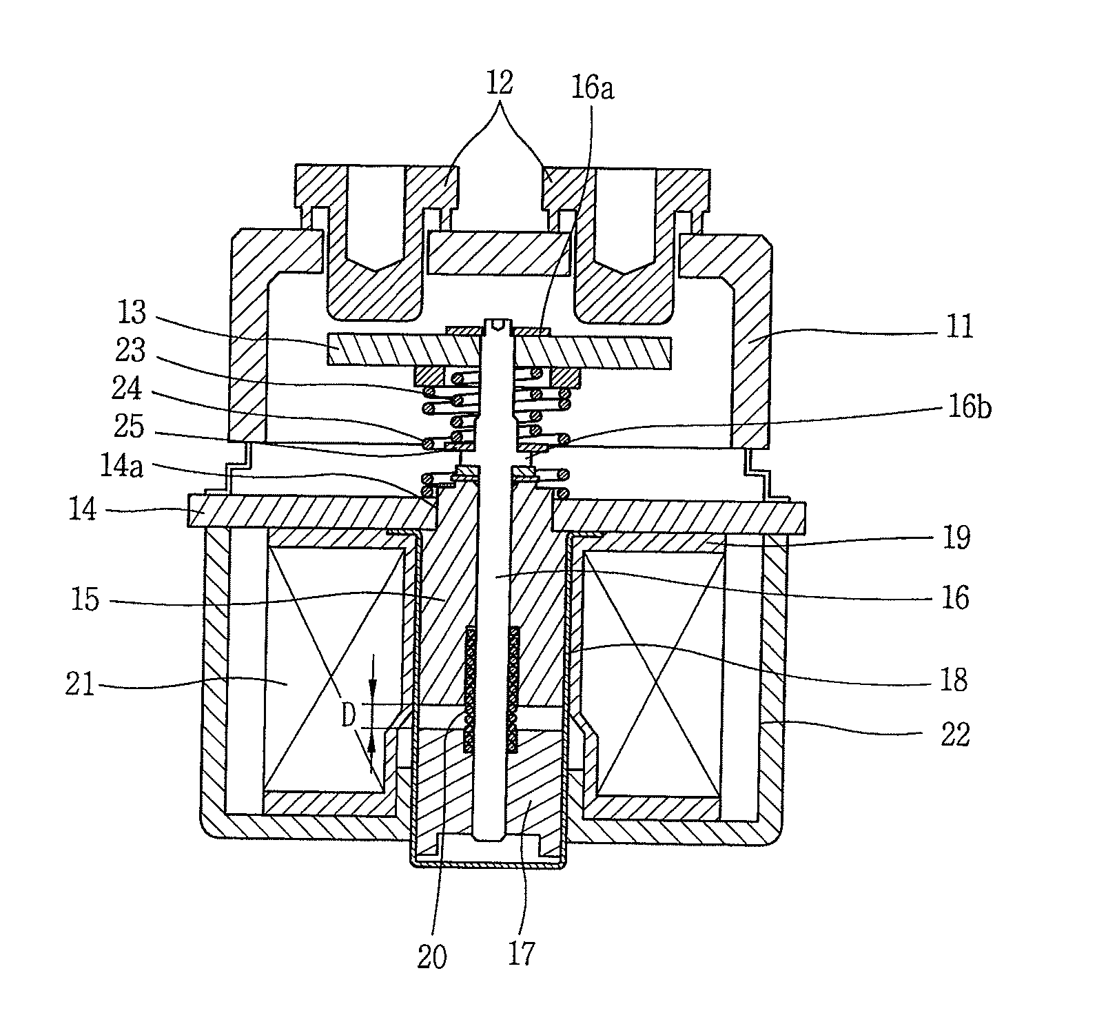
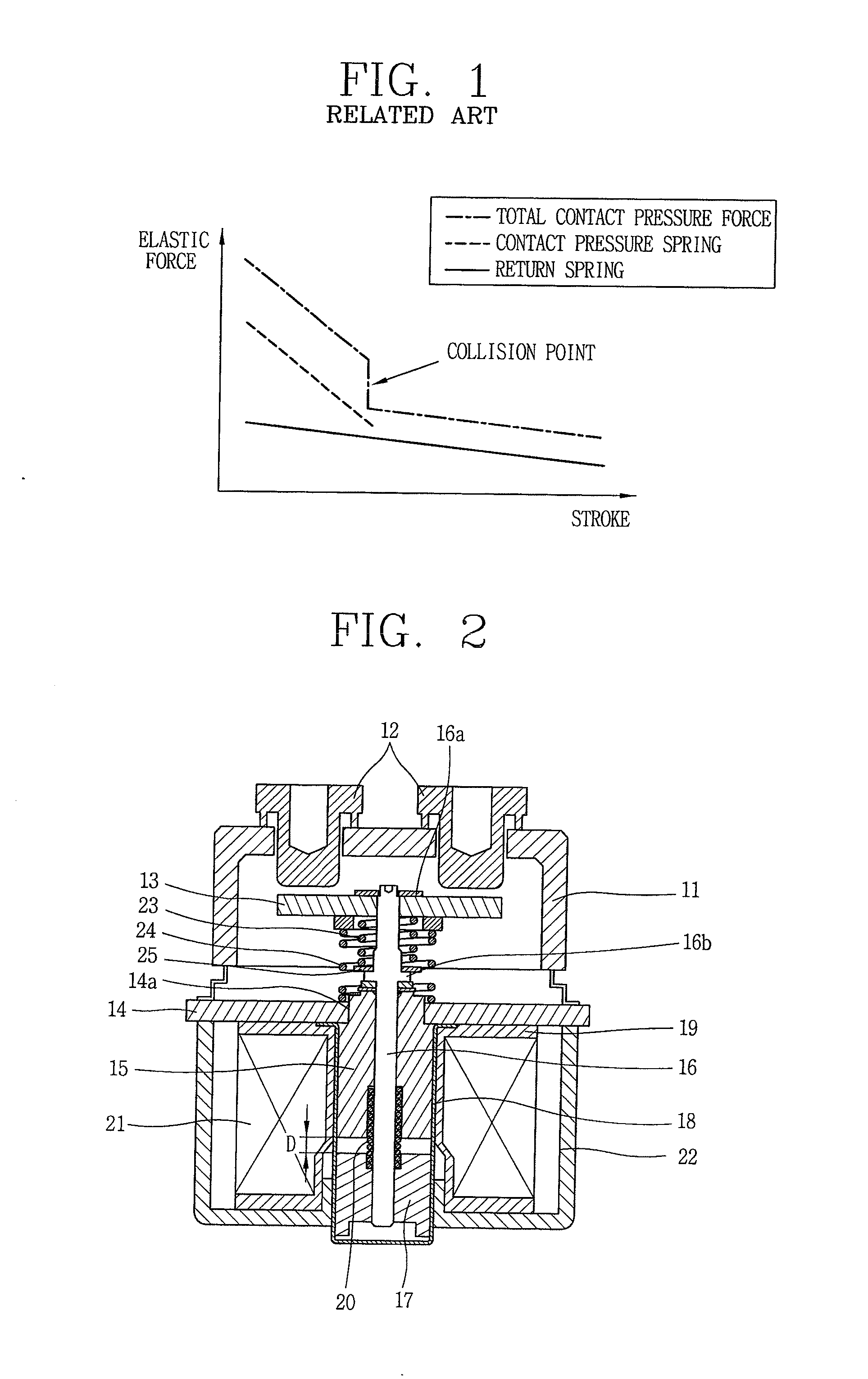
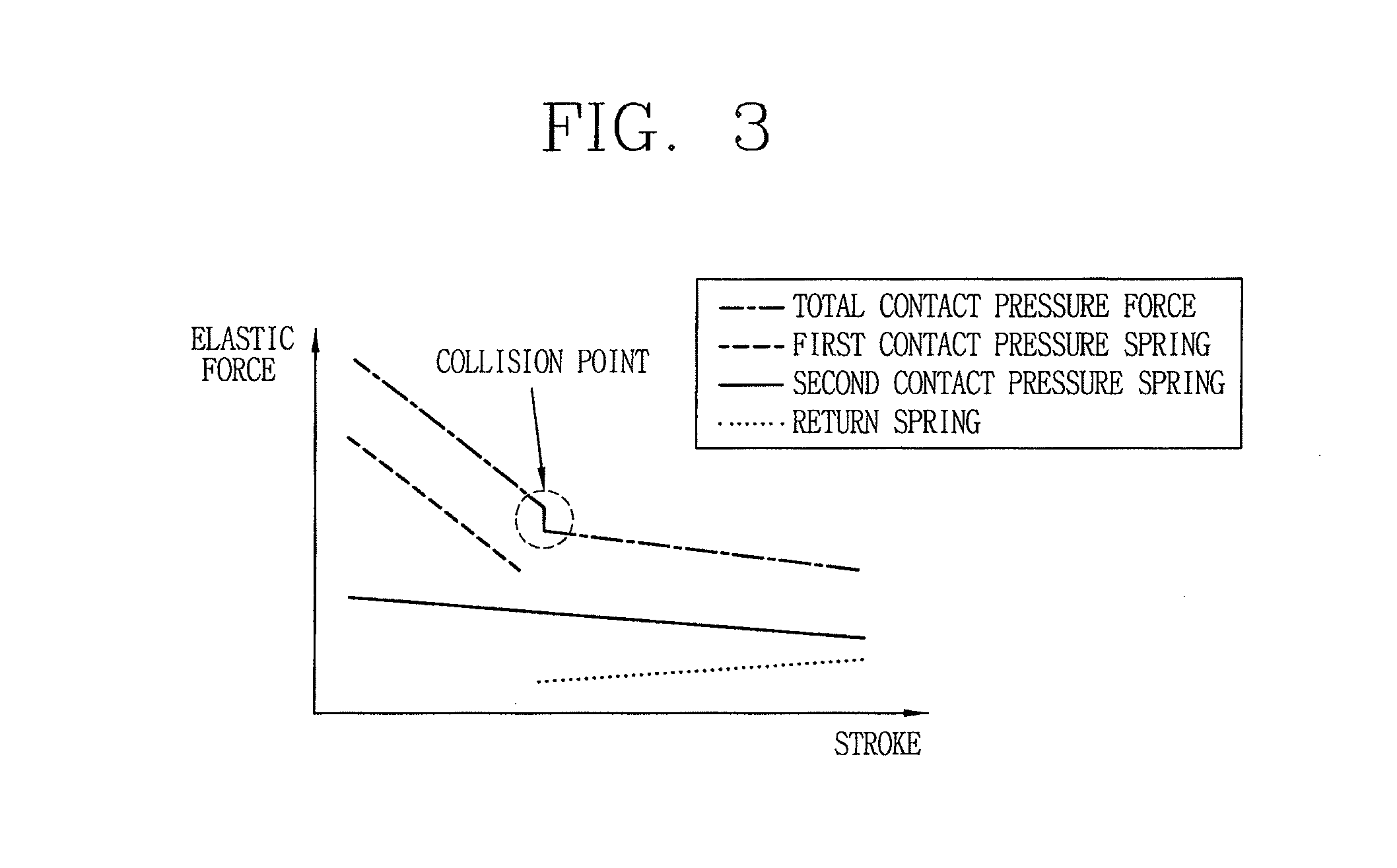
[0018]FIG. 2 is a vertical sectional view showing the configuration of a sealed cased magnetic switch according to the preferred embodiment of the present invention, and FIG. 3 is a graph showing a change in an elastic force over a contact position moving stroke of a movable contactor in a sealed cased magnetic switch according to the preferred embodiment of the present invention illustrated in FIG. 2, specifically, showing a change in an elastic force and a total contact pressure of a return spring and first and second contact pressure springs.

[0019]As shown in FIG. 2, a sealed cased magne...


PUM


Abstract

A sealed cased magnetic switch includes: a first contact pressure spring having one end supported by the movable contactor and applying an elastic force to the movable contactor to provide a contact pressure in a direction in which the movable contactor is brought into contact with the fixed electrode; a spring seat member supporting the other end of the first contact pressure spring and fixedly installed on the driving shaft; and a second contact pressure spring having a diameter larger than that of the first contact pressure spring and applying an elastic force at an outer position in a radial direction compared with the first contact pressure spring to the movable contactor in a direction in which the movable contactor is brought into contact with the fixed electrode.

Description

CROSS-REFERENCE TO A RELATED APPLICATION[0001]Pursuant to 35 U.S.C. §119(a), this application claims the benefit of earlier filing date and right of priority to Korean Application No. 10-2009-0136230, filed on Dec. 31, 2009, the contents of which is incorporated by reference herein in its entirety.BACKGROUND OF THE INVENTION[0002]1. Field of the Invention[0003]The present invention relates to a sealed cased magnetic switch and, more particularly, to a sealed cased magnetic switch capable of reducing noise of a switching operation.[0004]2. Description of the Related Art[0005]A magnetic switch, a device used for switch a power supply line, is a relatively low voltage electric power switch utilized for extensive purposes including an industrial purpose, a household purpose, electric vehicle purpose, and the like. The magnetic switch is configured to switch a power supply circuit by moving a movable contact connected to a movable core, to a circuit opening position where a movable conta...

Claims


Application Information

Patent Timeline
Patent Type & Authority Applications(United States)
IPC IPC(8): H01H36/00
CPCH01H1/242H01H9/04H01H50/023H01H51/065H01H50/546H01H50/56H01H50/22
Inventor EUM, YOUNG HWAN
Owner LS IND SYETEMS CO LTD
Why Eureka
Try Eureka