Reactor-use component and reactor

a technology of reactors and components, applied in the field of reactors, to achieve the effect of improving the workability of assembling into a reactor

Inactive Publication Date: 2011-06-30
SUMITOMO ELECTRIC IND LTD
View PDF8 Cites 81 Cited by
  • Summary
  • Abstract
  • Description
  • Claims
  • Application Information

AI Technical Summary

Benefits of technology

[0069]With the reactor-use component of the present invention, because the internal resin portion retains the coil in a state incapable of expanding...

Problems solved by technology

Normally, the coil before being assembled into a reactor has a clearance b...

Method used


Image

  • Reactor-use component and reactor
  • Reactor-use component and reactor
  • Reactor-use component and reactor

Examples


embodiment 1

Embodiment 1-1

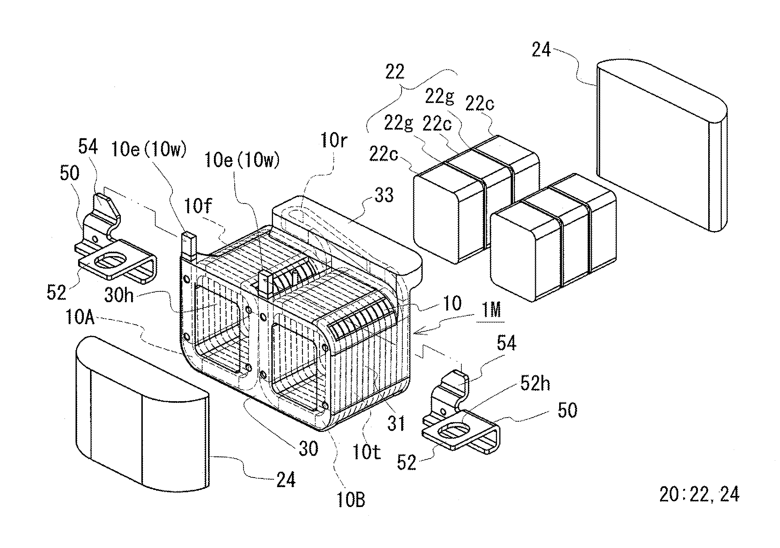
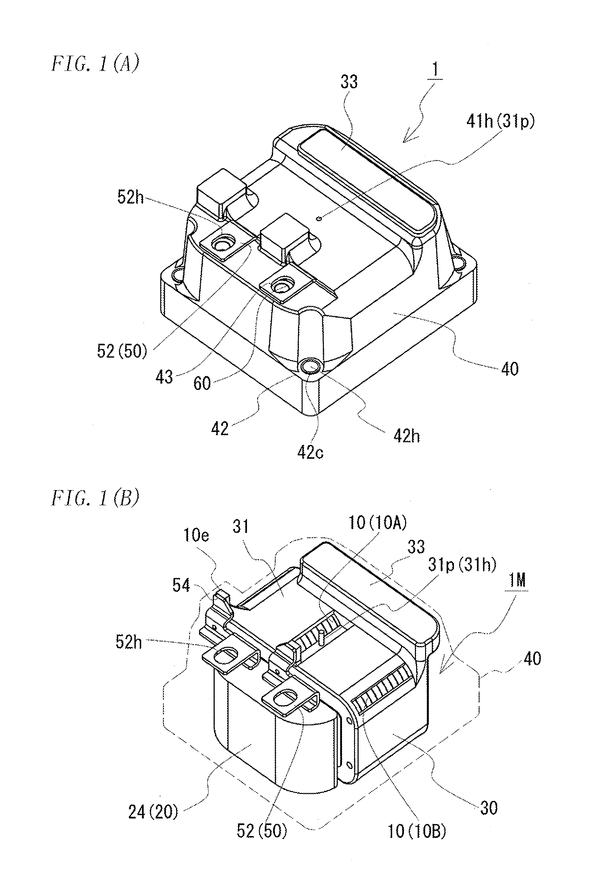
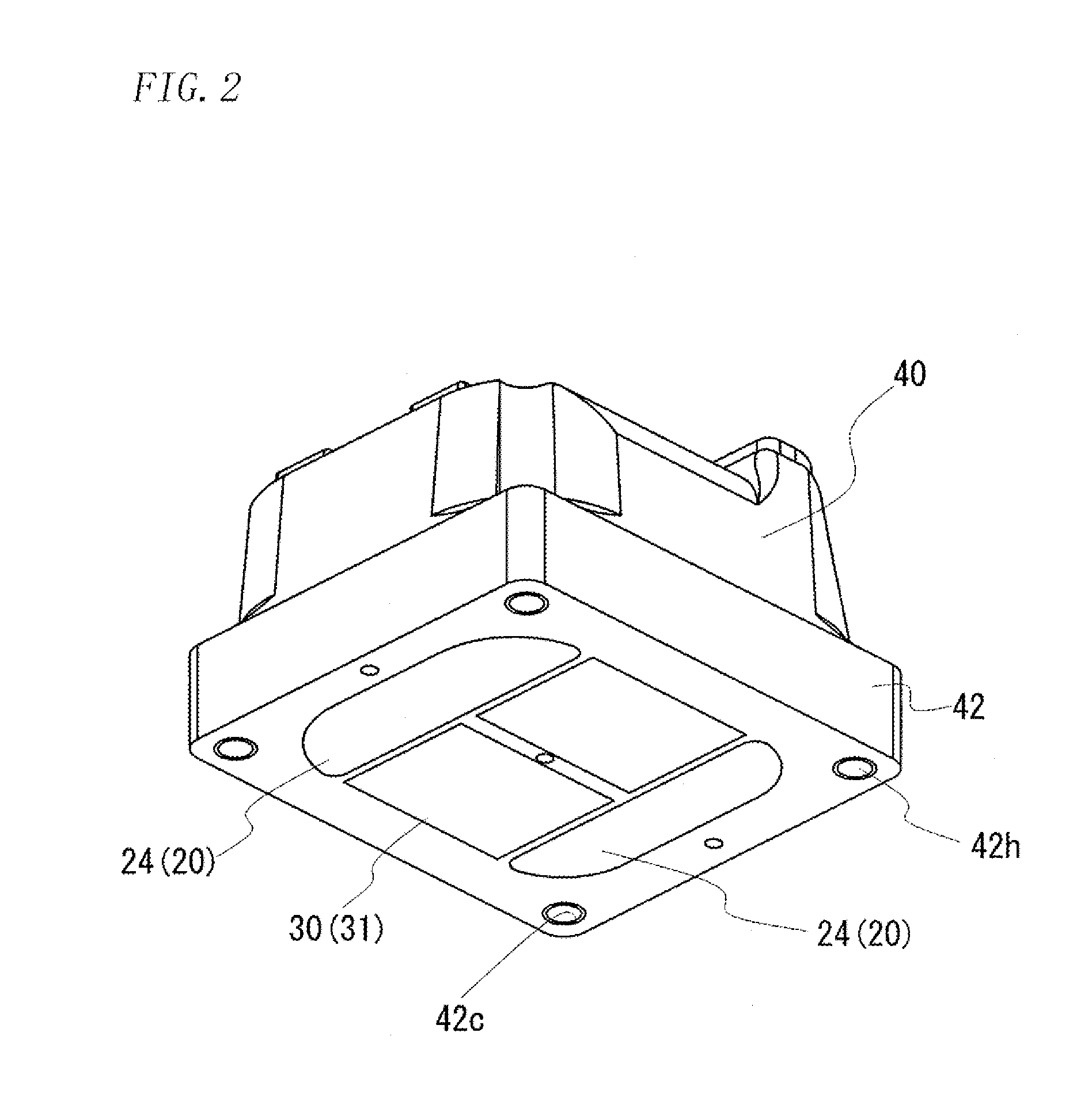
[0144]A reactor according to Embodiment 1-1 of the present invention will be described with reference to FIGS. 1 to 5.

[0145]A reactor 1 is structured with an assembled product made up of a coil molded product 1M in which a coil 10 is subjected to molding of an internal resin portion 30 and an annular core 20, wherein the assembled product covered by an external resin portion 40 (FIGS. 1 and 2). The core 20 includes internal core portions 22 (FIG. 3) fitted inside the coil 10, and exposed core portions 24 that connect between end faces of the internal core portions 22 and that are exposed outside the coil 10. Further, terminal fittings 50 are integrated by molding of the external resin portion 40, and nut accommodating holes 43 are formed by the molding as well. Nuts 60 fitted into the nut accommodating holes 43 and the terminal fittings 50 structure a terminal block.

[0146]The reactor 1 is used as a constituent of a DC-DC converter for hybrid vehicles, for example. In s...

embodiment 1-2

[0191]In Embodiment 1-1, it has been described that, in the second molding step, the assembled product is accommodated in the mold in an upside-down state when the external resin portion 40 is molded. On the other hand, the assembled product may be accommodated in the mold in an erect state. In such a case, the convex and concave portions formed at the internal bottom face of the base of the mold in Embodiment 1-1 should be formed on the lid side; and conversely, the internal bottom face of the mold should be formed as a flat face. Further, it is preferable that the base can be divided into the bottom face and the side faces such that the reactor 1 can easily be taken out from the mold. In this manner, even when the assembled product is placed in an erect state, the reactor similarly to that according to Embodiment 1-1 can easily be formed. In this case, the concave portion into which the couple portion covering portion 33 of the assembled product is fitted may be window-shaped, whe...

embodiment 2

Embodiment 2-1

[0192]Next, with reference to FIGS. 6 to 9, a description will be given of an embodiment using a core integrated type coil molded product, which is the integrated coil and internal core portions formed by molding of the internal resin portion.

[0193]The major difference of the Embodiment 1-1 from the present embodiment lies in that the internal core portions are integrated by molding of the internal resin portion, and the rest of the structure is substantially identical to that of Embodiment 1-1. Therefore, in the following, a description will be given focusing on the difference.

[0194]As shown in FIG. 6, this core integrated type coil molded product 1MC includes a coil 10, internal core portions 22 fitted into the coil 10, and an internal resin portion 30 that is molded so as to integrate the coil 10 and the internal core portions 22. As shown in FIG. 7, the coil 10 according to the present embodiment is similarly structured as the coil 10 according to Embodiment 1-1 ex...


PUM


Abstract

A reactor-use component which provides improved workability in assembling into a reactor, and a reactor using the component are provided. The reactor-use component is for structuring a reactor including a coil 10 formed with a pair of paralleled coil elements 10A and 10B made of a spirally wound wire and a core 20 fitted into the coil elements 10A and 10B to form an annular shape. The reactor-use component includes an internal resin portion 30 that retains a shape of the coil 10, and hollow bores 30h formed by a part of the internal resin portion 30 for fitting the core 20 to inner circumferences of the coil elements 10A and 10B. By inserting internal core portions 22 into the hollow bores 30h and joining opposite ends of the internal core portions 22 to exposed core portions 24, the reactor 1 can be obtained. Because the internal resin portion 30 retains the coil 10 in a state incapable of expanding or compressing, the workability in assembling into the reactor 1 can be improved.

Description

TECHNICAL FIELD[0001]The present invention relates to a reactor used as a component of a converter or the like, and to a reactor-use component structuring the reactor.BACKGROUND ART[0002]In hybrid vehicles having been gaining popularity in recent years, a converter that boosts up and steps down a voltage is used. One known component of the converter is a reactor disclosed in Patent Document 1.[0003]The main constituents of the reactor are an annular core made of a magnetic material, and a coil formed of a wound wire such as a rectangular wire. In assembling the reactor, for example, the rectangular wire is previously wound edgewise, to form a pair of coil elements. The pair of coil elements are coupled in parallel to each other by a couple portion. Then, into inner circumferences of the coil elements, internal core portions made up of a plurality of core pieces and gap members are fitted. Thereafter, two end faces of the internal core portions are coupled to each other on exposed co...

Claims


Application Information

Patent Timeline
IPC IPC(8): H01F27/29H01F30/00
CPCH01F27/306H01F37/00H01F27/327
Inventor KATO, MASAYUKIKANTO, TAKUJIITO, ATSUSHIYAMAMOTO, SHINICHIROKAWAGUCHI, HAJIMENII, KAZUHIKO
Owner SUMITOMO ELECTRIC IND LTD
Why Eureka
Try Eureka