System and method for runtime determination of camera miscalibration

a camera and runtime determination technology, applied in the field of vision system camera calibration, can solve the problems of affecting the actual camera position and lens distortion, difficult to trace the root cause of application's deteriorating performance, and time-consuming and labor-intensive calibration tasks, etc., to achieve faster, less-expensive and more-straightforward diagnosis.

Active Publication Date: 2011-06-30
COGNEX CORP
View PDF21 Cites 136 Cited by
  • Summary
  • Abstract
  • Description
  • Claims
  • Application Information

AI Technical Summary

Benefits of technology

[0008]This invention provides a system and method for runtime determination (self-diagnosis) of camera miscalibration (accuracy), typically related to camera extrinsics, based on historical statistics of runtime measurements of objects acquired in the scene. One example of the runtime measurement is alignment score, which is defined based on matching of observed and expected image data of trained object models. This arrangement avoids a need to cease runtime operation of the vision system and/or stop the production line that is served by the vision system to diagnose if the sy

Problems solved by technology

As calibration is a demanding and time-consuming task, undertaken by skilled technicians, it is best performed only when actually required.
However, when the vision system operates in adverse environment, such as a manufacturing line, the actual camera position and lens distortions may change due to thermal expansion, vibration, inadvertent focus change, etc.
Furthermore, even if a machine vision application is performing suboptimally, it may be difficult to trace the root cause of the application's deteriorating performance due to camera miscalibration.
This validation procedure shortens the system downtime significantly because t

Method used


Image

  • System and method for runtime determination of camera miscalibration
  • System and method for runtime determination of camera miscalibration
  • System and method for runtime determination of camera miscalibration

Examples


Embodiment Construction

A. System Overview and Calibration

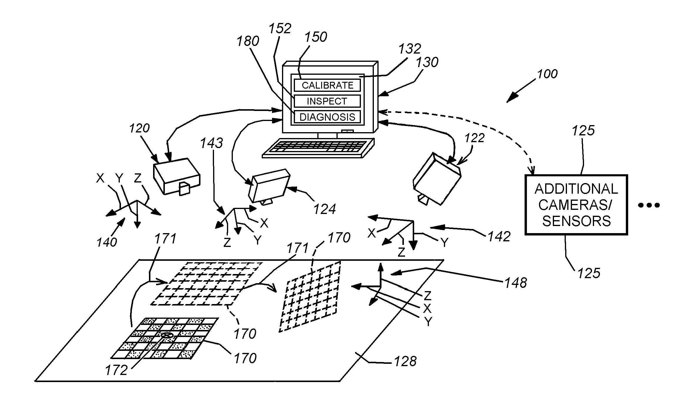
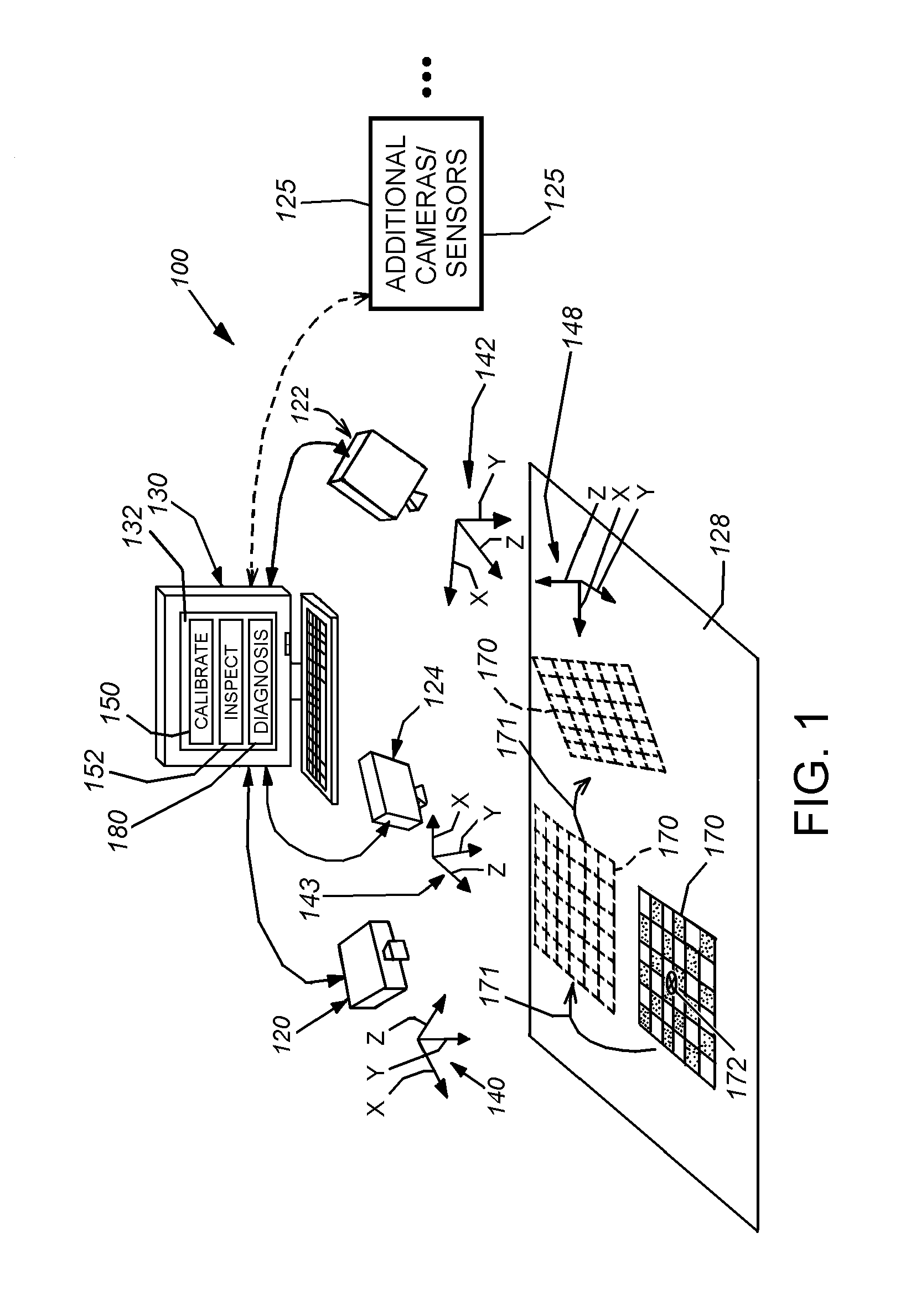
[0021]FIG. 1 depicts a typical arrangement for a vision system 100 for determining the two-dimensional (2D) or three-dimensional (3D) alignment, or pose, of a viewed scene that can include one or more runtime objects to be inspected, aligned, acted upon by a robot manipulator, or any other operation that is controlled or assisted by machine vision processes. The system can be calibrated (and calibration can be later self-diagnosed) according to an illustrative embodiment of this invention.

[0022]In general, the system 100 can be any vision system arrangement containing at least three cameras having the object-containing scene 128 within its field of view. The camera(s) or sensor(s) 120, 122, 124 can each comprise a 2D camera as shown, or optionally, a 3D sensor. Where provided, a 3D sensor can be adapted to generate depth images of a scene using optical triangulation between two discrete cameras (binocular vision) within a stereo camera head, separat...


PUM


Abstract

This invention provides a system and method for runtime determination (self-diagnosis) of camera miscalibration (accuracy), typically related to camera extrinsics, based on historical statistics of runtime alignment scores for objects acquired in the scene, which are defined based on matching of observed and expected image data of trained object models. This arrangement avoids a need to cease runtime operation of the vision system and/or stop the production line that is served by the vision system to diagnose if the system's camera(s) remain calibrated. Under the assumption that objects or features inspected by the vision system over time are substantially the same, the vision system accumulates statistics of part alignment results and stores intermediate results to be used as indicator of current system accuracy. For multi-camera vision systems, cross validation is illustratively employed to identify individual problematic cameras. The system and method allows for faster, less-expensive and more-straightforward diagnosis of vision system failures related to deteriorating camera calibration.

Description

FIELD OF THE INVENTION[0001]This invention relates to vision systems and more particularly to calibration of vision system cameras.BACKGROUND OF THE INVENTION[0002]Machine vision systems are commonly employed in industry to determine the alignment of parts and objects with respect to a predetermined two-dimensional (2D) or three-dimensional (3D) coordinate space. These systems employ various techniques and programs to determine alignment of objects, often based on trained models of the objects. Camera calibration is an essential step in computer vision—both in two-dimensional (2D) and three-dimensional (3D) imaging systems. Camera calibration involves modeling a camera's position and lens characteristics known as the extrinsic and intrinsic parameters. Camera calibration can be performed on either a single camera or a multi-camera arrangement, such as a system that includes one or more stereo camera heads. Stereo camera heads, and other forms of 3D sensors, enable the generation of ...

Claims


Application Information

Patent Timeline
IPC IPC(8): H04N17/00
CPCG06T7/002G06T2207/30108G06T2207/10012G06T7/85
Inventor YE, XIANGYUNLI, DAVID Y.SHIVARAM, GURUPRASADMICHAEL, DAVID J.
Owner COGNEX CORP
Why Eureka
Try Eureka