Image forming apparatus and image forming system

a technology of image forming apparatus and image forming system, which is applied in the direction of electrographic process apparatus, digital output to print units, instruments, etc., can solve the problems of large the central administration apparatus cannot recognize the status of use of expendable parts or said parts, and the part dismounted from the image forming apparatus when the part is replaced, so as to reduce the burden on the service engineer

Inactive Publication Date: 2011-06-30
KONICA MINOLTA BUSINESS TECH INC
View PDF3 Cites 9 Cited by
  • Summary
  • Abstract
  • Description
  • Claims
  • Application Information

AI Technical Summary

Benefits of technology

[0011]The present invention has one aspect to solve the above problems and an object of the present invention is to provide an image forming apparatus and an image forming system which recogniz

Problems solved by technology

Incidentally, the image forming apparatus of Patent document 1 can place the order for the expendable part or the part warned about replacing, however there is a problem that the central administration apparatus can not recognize statuses of use of the expendable part or said part.
Also, the information processing apparatus disclosed in Patent Document 2 can administrate the operation life of the part by recovering a correct count value, even if a user cancels the count value for the status o

Method used


Image

  • Image forming apparatus and image forming system
  • Image forming apparatus and image forming system
  • Image forming apparatus and image forming system

Examples


first embodiment

[Exemplary Configuration of Image Forming System 100]

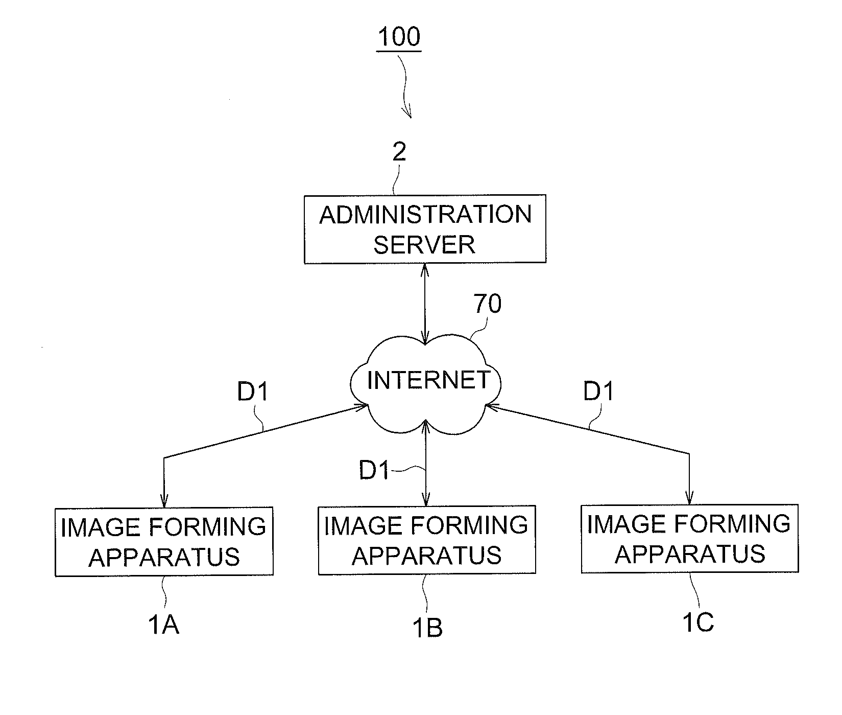
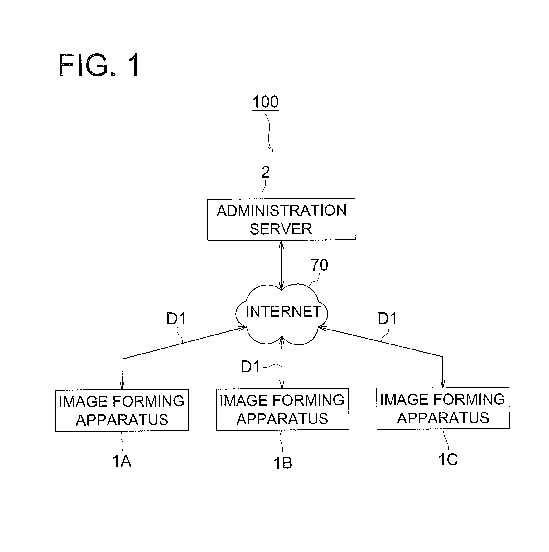
[0028]FIG. 1 is a block diagram showing an exemplary configuration of an image forming system 100 related to a first embodiment. As FIG. 1 shows, the image forming system 100 is configured with image forming apparatuses 1A, 1B, and 1C, and an administration server 2. The image forming apparatuses 1A, 1B, and 1C, are, for example, a printer, a copying machine and a multifunction peripheral.

[0029]The image forming apparatuses 1A, 1B, and 1C are connected with the administration server 2 via Internet 70 representing an exemplary network. The image forming apparatuses 1A, 1B, and 1C are provided with the image forming units which are mounted in a detachable manner at the image forming sections to form the image. The image forming unit is provided with a memory to store unit information D1 including identification data and information of times of use. The image forming apparatuses 1A, 1B, and 1C read out the unit information D1 from th...

second embodiment

[0063]In the present embodiment, an image forming apparatus 3 in which a memory 80a is provided in the control section 10 of the image forming apparatus 1A will be described. Since elements having the same names or the same symbols have the some functions, descriptions thereof are omitted.

[Exemplary Configuration of Image Forming Apparatus 3]

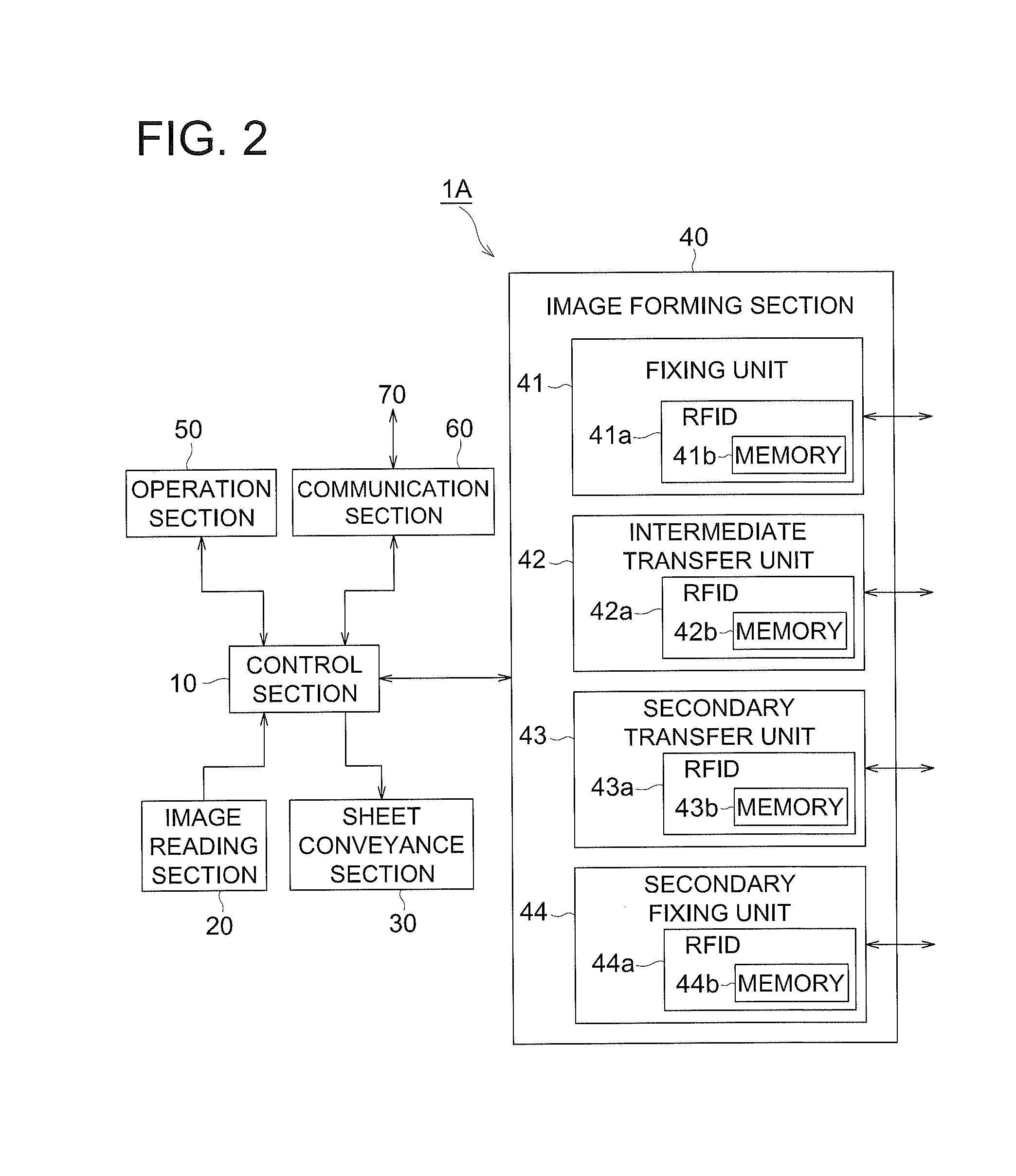
[0064]FIG. 8 is a block diagram showing an exemplary configuration of a control system of an image forming apparatus 3 related to a second embodiment. As FIG. 8 shows, the image forming apparatus 3 is configured with a control section 80, an image reading section 20, a sheet conveyance section 30, an image forming section 40, an operation section 50 and a communication section 60.

[0065]To the control section 80, the image reading section 20, the sheet conveyance section 30, the image forming section 40, the operation section 50 and the communication section 60. The control section 80 controls the image reading section 20, the sheet conveyance se...


PUM


Abstract

In an image forming system configured with image forming apparatuses and an administration server connected with the image forming apparatuses thereof via Internet, the image forming unit, mounted at the image forming section in a detachable manner, stores unit information which includes identification data and information of times of use. An operation section creates unit replacing permission information to permit the image forming unit to be dismounted from the image forming section. A control section receives the unit replacing permission information and reads out the unit information. The communication section transmits the unit information to the administration server. Whereby, the administration server can recognize the image forming unit dismounted from the image forming section and the times of used of the image forming unit just before dismounting, therefore the burden of the service engineer can be reduced.

Description

[0001]This application is based on Japanese Patent Application No. 2009-293253 filed on Dec. 24, 2009, in Japanese Patent Office, the entire content of which is hereby incorporated by reference.TECHNICAL FIELD[0002]The present invention relates to an image forming apparatus and an image forming system connected with an administration server to control an image forming section to form an image from a remote location.BACKGROUND OF THE INVENTION[0003]Generally, in an image forming apparatus such as a printer, copying machine and multifunction peripheral, a toner image is formed by a developing device on an image carrier such as photoconductive drum, the image is transferred onto an intermediate transfer belt, and the image is transferred onto a sheet from the intermediate transfer belt so as to form the image on the sheet. Remaining toner adhering on the photoconductive drum after transferring the toner image is removed from an outer circumferential surface of the photoconductive drum ...

Claims


Application Information

Patent Timeline
IPC IPC(8): G06F3/12
CPCG03G15/5075G03G2215/00113H04N1/00344H04N1/00832H04N1/32122H04N2201/3278H04N2201/0039H04N2201/0049H04N2201/0082H04N2201/3205H04N2201/3274H04N1/32523
Inventor FURUKAWA, HIROSHI
Owner KONICA MINOLTA BUSINESS TECH INC
Why Eureka
Try Eureka