Miniaturized liquid cooling apparatus and electronic device incorporating the same

a liquid cooling device and miniaturized technology, applied in lighting and heating apparatuses, positive displacement liquid engines, semiconductor/solid-state device details, etc., can solve the problems of increasing the size the inability of the liquid cooling device to properly cool the electronic components, and the need for compact electronic products

Inactive Publication Date: 2011-06-30
HON HAI PRECISION IND CO LTD
View PDF7 Cites 8 Cited by
  • Summary
  • Abstract
  • Description
  • Claims
  • Application Information

AI Technical Summary

Problems solved by technology

However, when the electronic component is inversely mounted on a bottom side of the mainboard and the notebook computer is oriented on a flat support, the working fluid in the heat absorbing member cannot contact the heat-absorbing plate of the heat absorbing member unless the working fluid is fully filled in the heat absorbing member.
If the working fluid is not fully filled in the heat absorbing member, the liquid cooling device cannot properly cool the electronic component.
Further, the pump and the tubes occupy a large volume, which increases the size of the liquid cooling device.
This goes against the need for compact size in electronic products.

Method used


Image

  • Miniaturized liquid cooling apparatus and electronic device incorporating the same
  • Miniaturized liquid cooling apparatus and electronic device incorporating the same
  • Miniaturized liquid cooling apparatus and electronic device incorporating the same

Examples


Embodiment Construction

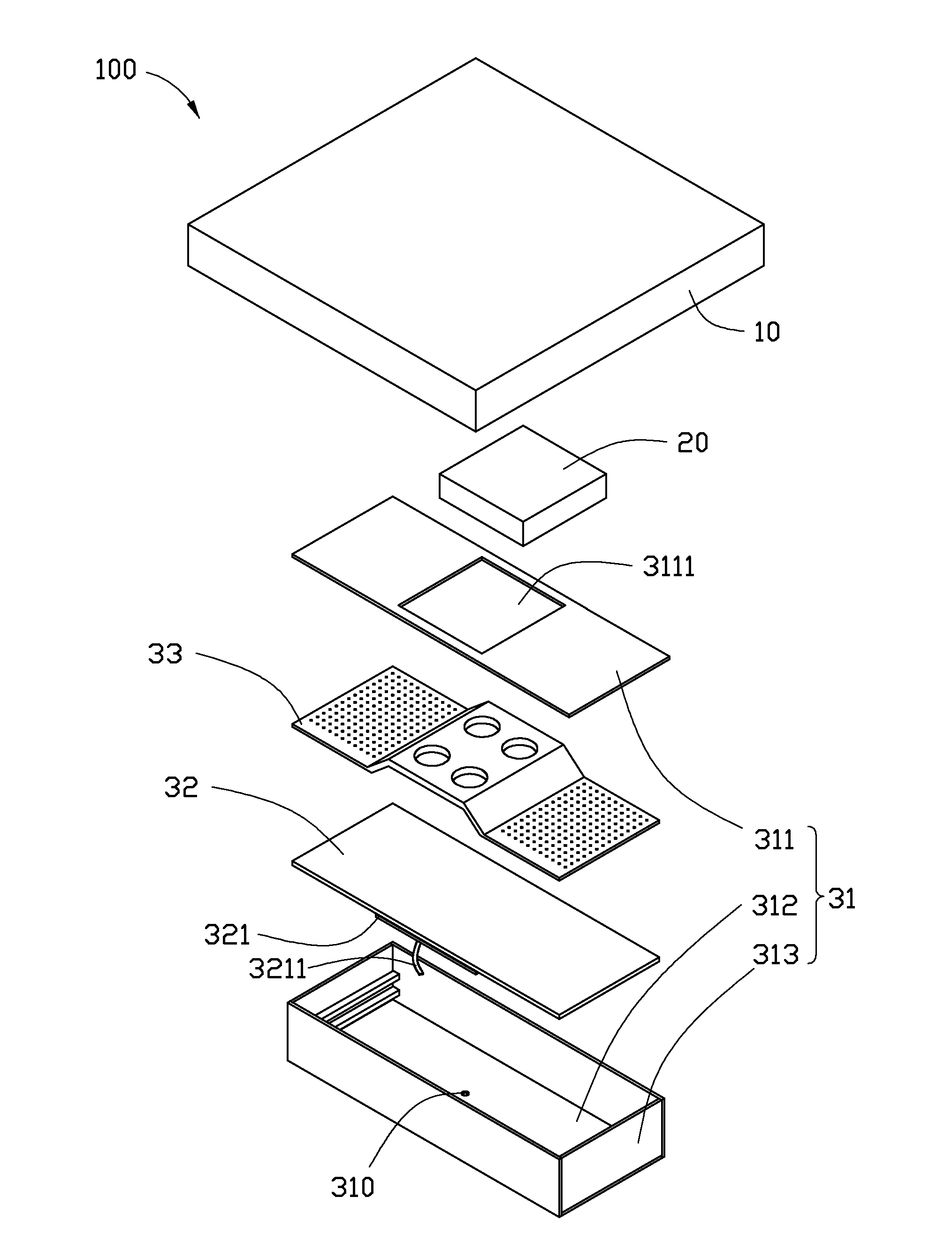
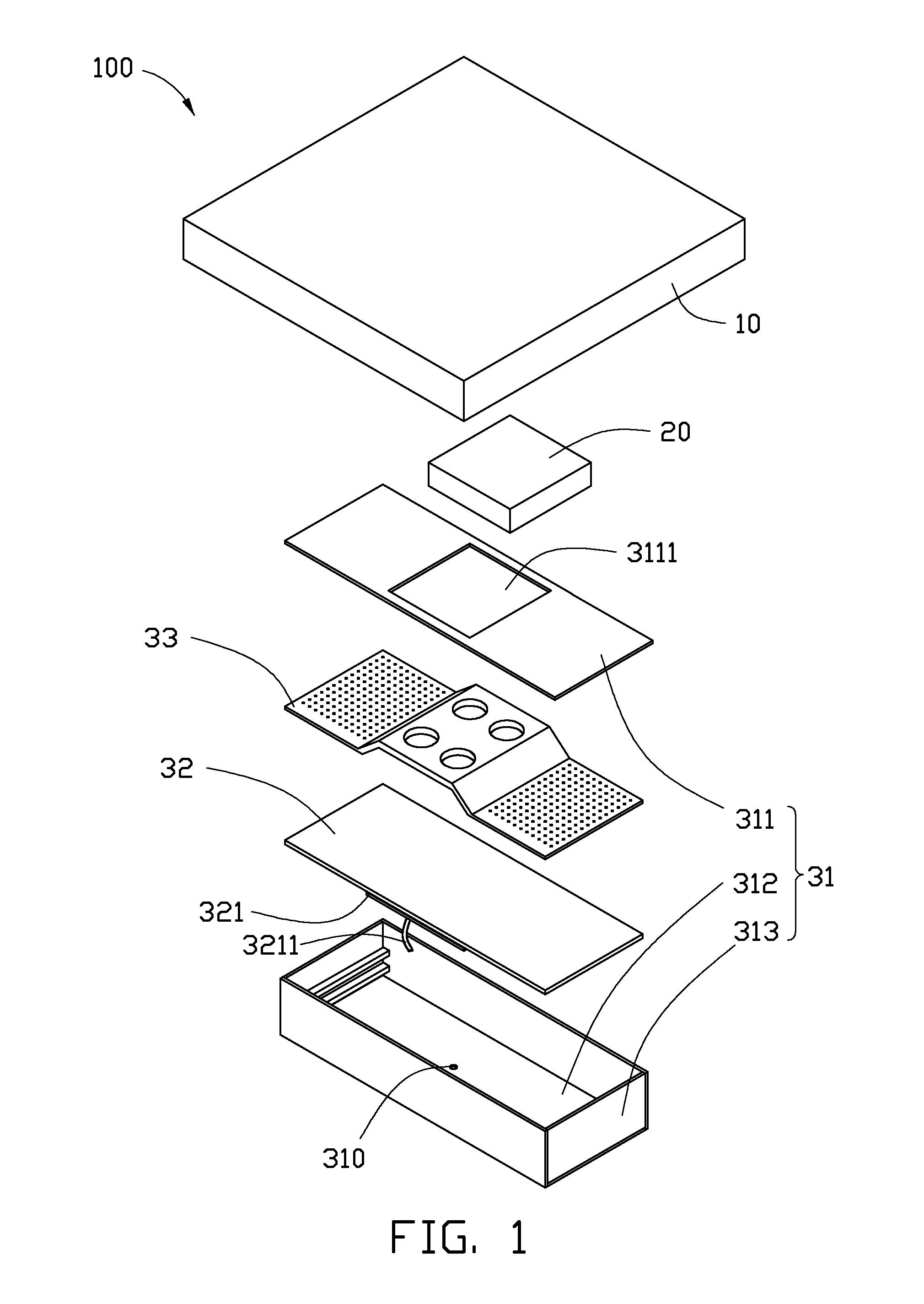
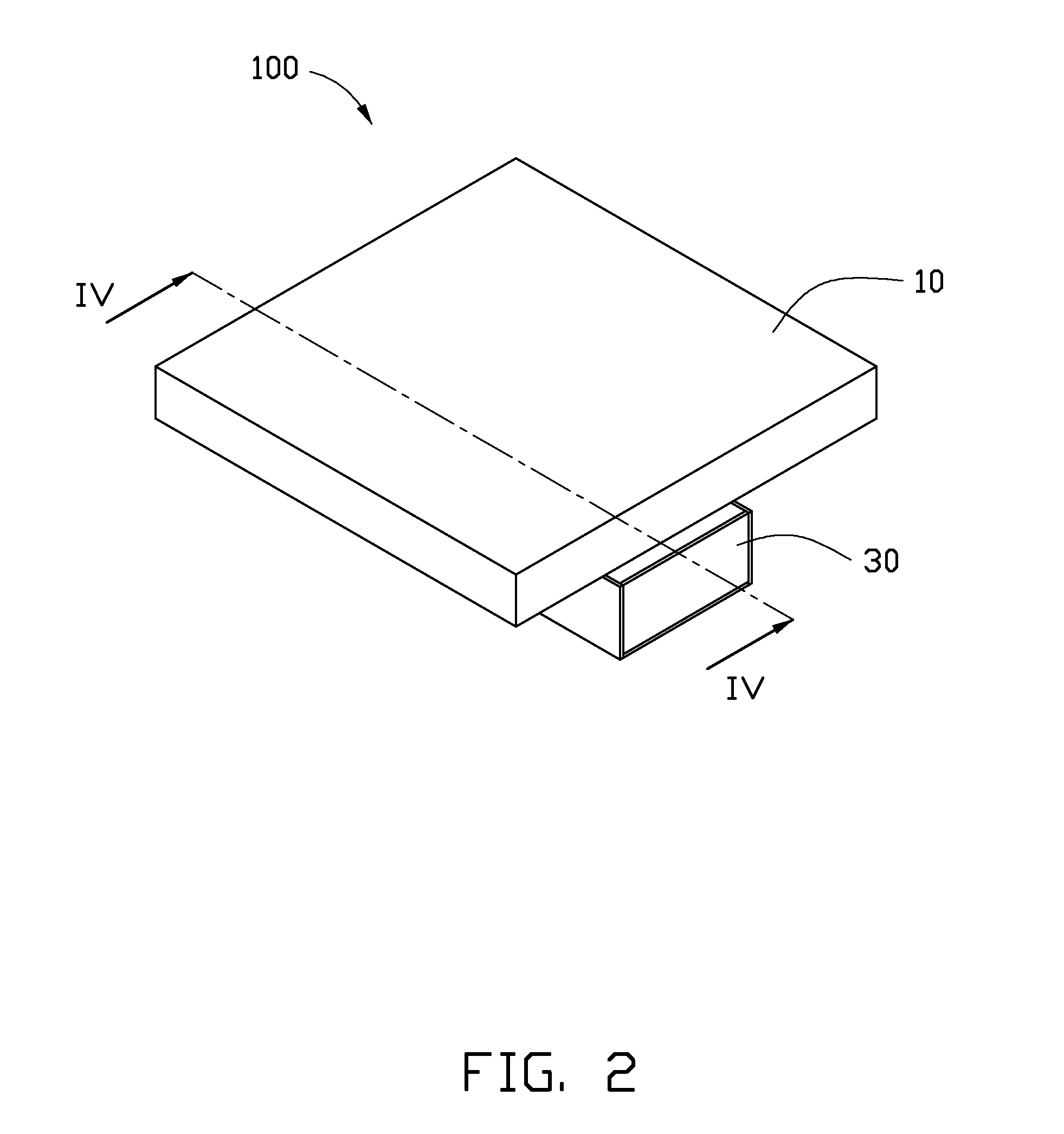
[0012]Referring to FIGS. 1-2, an electronic device 100 according to an exemplary embodiment of the present disclosure is shown. The electronic device 100 includes a mainboard 10, an electronic component 20 such as a central processing unit, and a miniaturized liquid cooling apparatus 30 for cooling the electronic component 20. The electronic component 20 is mounted on the mainboard 10, and is located at a bottom side of the mainboard 10. The liquid cooling apparatus 30 is located under the bottom side of the mainboard 10, and is attached to the electronic component 20. The liquid cooling apparatus 30 includes a casing 31, and a diaphragm 32 and a partition plate 33 received in the casing 31.

[0013]Referring also to FIG. 4, the casing 31 is a rectangular box. The casing 31 includes a top plate 311, a bottom plate 312, and a sidewall 313 connected between the top plate 311 and the bottom plate 312. The casing 31 defines a receiving room 34 therein. The diaphragm 32 is arranged in the r...


PUM


Abstract

A liquid cooling apparatus for cooling an inversely mounted electronic component, includes a casing defining a receiving room therein, a diaphragm, a partition plate forming a nozzle thereon, and a piezoelectric element attached to the diaphragm in such a manner that that a vibrating direction thereof is perpendicular to the diaphragm. The diaphragm is arranged in the receiving room and divides the receiving room into a top first chamber and a bottom second chamber isolated from each other. The partition plate is arranged in the first chamber and divides the first chamber into an upper region and a lower region. The lower region is filled with a working fluid. When the diaphragm is driven to vibrate upwardly by the piezoelectric element, the diaphragm pushes the working fluid in the lower region of the first chamber to the upper region of the first chamber via the nozzle.

Description

BACKGROUND[0001]1. Technical Field[0002]The disclosure generally relates to liquid cooling apparatuses; and more particularly to a miniaturized liquid cooling apparatus, and an electronic device incorporating the miniaturized liquid cooling apparatus.[0003]2. Description of Related Art[0004]In an electronic device such as a notebook computer, a mainboard is usually mounted in a casing of the notebook computer, with main electronic components such as a central processing unit (CPU) and a video graphics array chip connected to the mainboard. In addition, a liquid cooling device is used for cooling the CPU mounted on the mainboard. Generally, the liquid cooling device includes a heat absorbing member attached to the CPU for absorbing heat generated by the CPU, a heat dissipation member dissipating the heat to the surrounding environment, a pump driving working fluid to circulate between the heat absorbing member and the heat dissipation member, and a plurality of tubes connecting the h...

Claims


Application Information

Patent Timeline
Patent Type & Authority Applications(United States)
IPC IPC(8): H05K7/20F28F23/00
CPCH01L23/427H01L2924/0002H01L2924/00
Inventor CHAO, CHIEN-YUCHEN, YEN-CHIH
Owner HON HAI PRECISION IND CO LTD
Why Eureka
Try Eureka