System, device, and method for determination of intraocular pressure

a technology of intraocular pressure and system, applied in the field of systems, devices, and methods for measuring intraocular pressure, can solve the problems of insufficient single-point measurements labor-intensive longer-term tonometry, and inability to fully manage eye diseas

Active Publication Date: 2011-06-30
IOPTIC INC +1
View PDF22 Cites 36 Cited by
  • Summary
  • Abstract
  • Description
  • Claims
  • Application Information

AI Technical Summary

Benefits of technology

The processing device may further perform the phase calculation using an integral transform and may calculate the phases at one or more spatial frequencies corresponding to peaks in an absolute value of the integral transform.
In accordance with one implementation, the anchoring member comprises a plate for insertion in a scleral pocket and for immobilizing the device, and an arm for entering an anterior chamber of the eye through a scleral tunnel. The plate may include holes for suturing the plate to the eye, and / or holes for assisting wound healing.
In accordance with yet another implementation, the device further includes a second intraocular pressure sensor having at least one of a different diameter, shape, membrane thickness, membrane material, and substrate material, such that the intraocular pressure sensor and the second intraocular pressure sensor provide at least one of redundant pressure measurement, failure detection, compensation for temperature fluctuations in the eye, increased pressure measurement sensitivity, and increased pressure measurement dynamic range.
Also according to this implementation, the material and dimensions of the flexible membrane may prevent the membrane from contacting the bottom of the sealed cavity under pressures encountered in the intraocular environment.

Problems solved by technology

However, these single-point measurements remain insufficient to fully manage eye disease, particularly glaucoma.
IOP peaks are missed in office hours measurements, IOP fluctuations may be an independent risk factor, and a majority of glaucoma patients require changes to their topical and / or surgical management approach after multiple IOP measurements on a single day.
Infrequent measurements also make it difficult to evaluate treatment effectiveness and / or to assess patient compliance.
However, more frequent, longer term tonometry is labor intensive, impractical, expensive, and often conducted only upon admission to an academic hospital.
Tonometers that can be used by the patient are know in the art, but these devices often cause discomfort, have proven difficult for patients to repeatably administer, and have demonstrated unacceptable error in clinical studies.
Readout of passive electronic sensors has proven problematic because inductively coupling to tiny receivers in the sensor is difficult.
Active sensors overcome this problem, but require implantable power sources or power storage systems, implanted integrated circuits, and large antennas.
As a result, both passive and active systems have so far proven too large and complex, mostly irreversible, risky with regard to biocompatibility, and / or error prone.

Method used


Image

  • System, device, and method for determination of intraocular pressure
  • System, device, and method for determination of intraocular pressure
  • System, device, and method for determination of intraocular pressure

Examples


Embodiment Construction

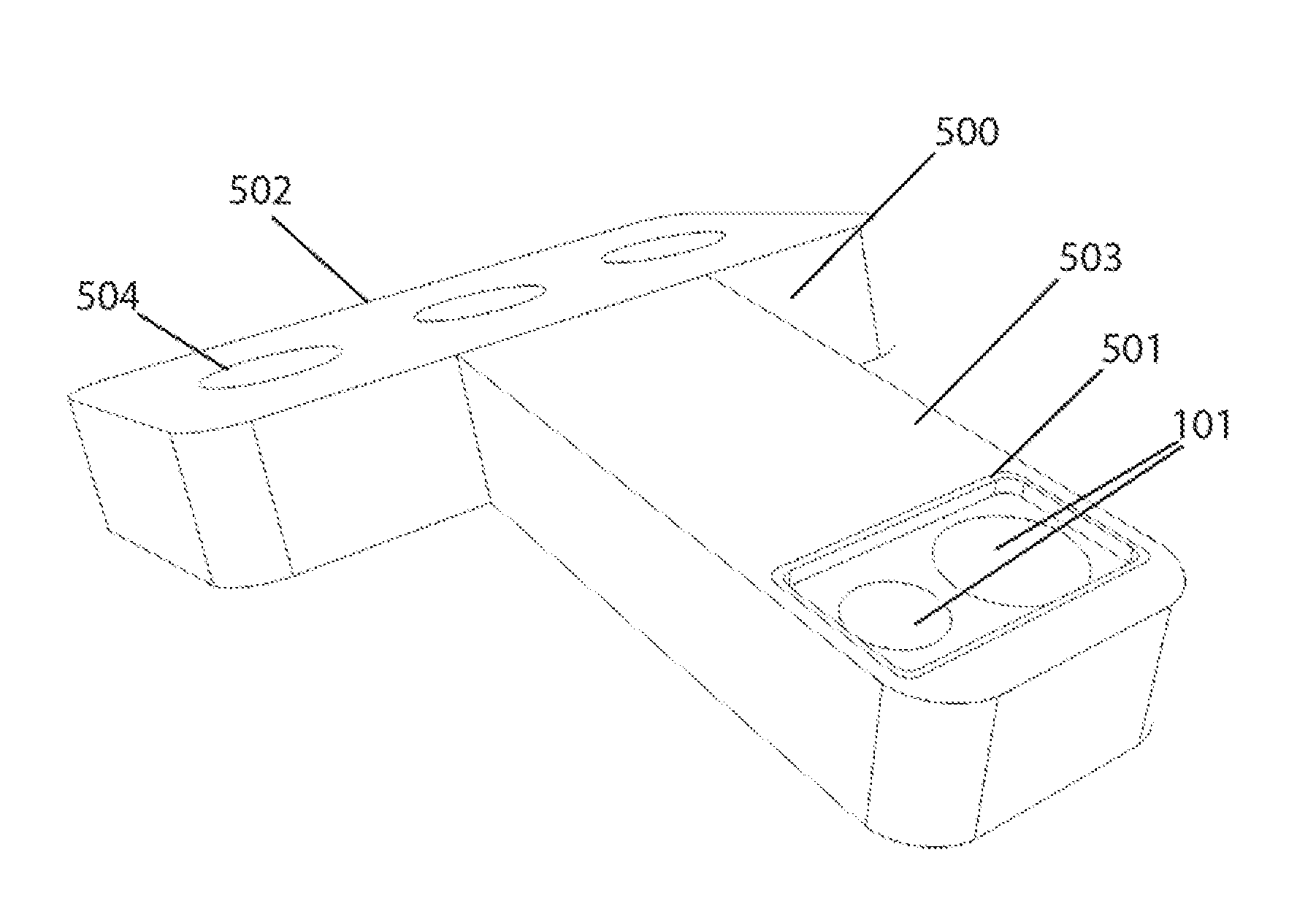
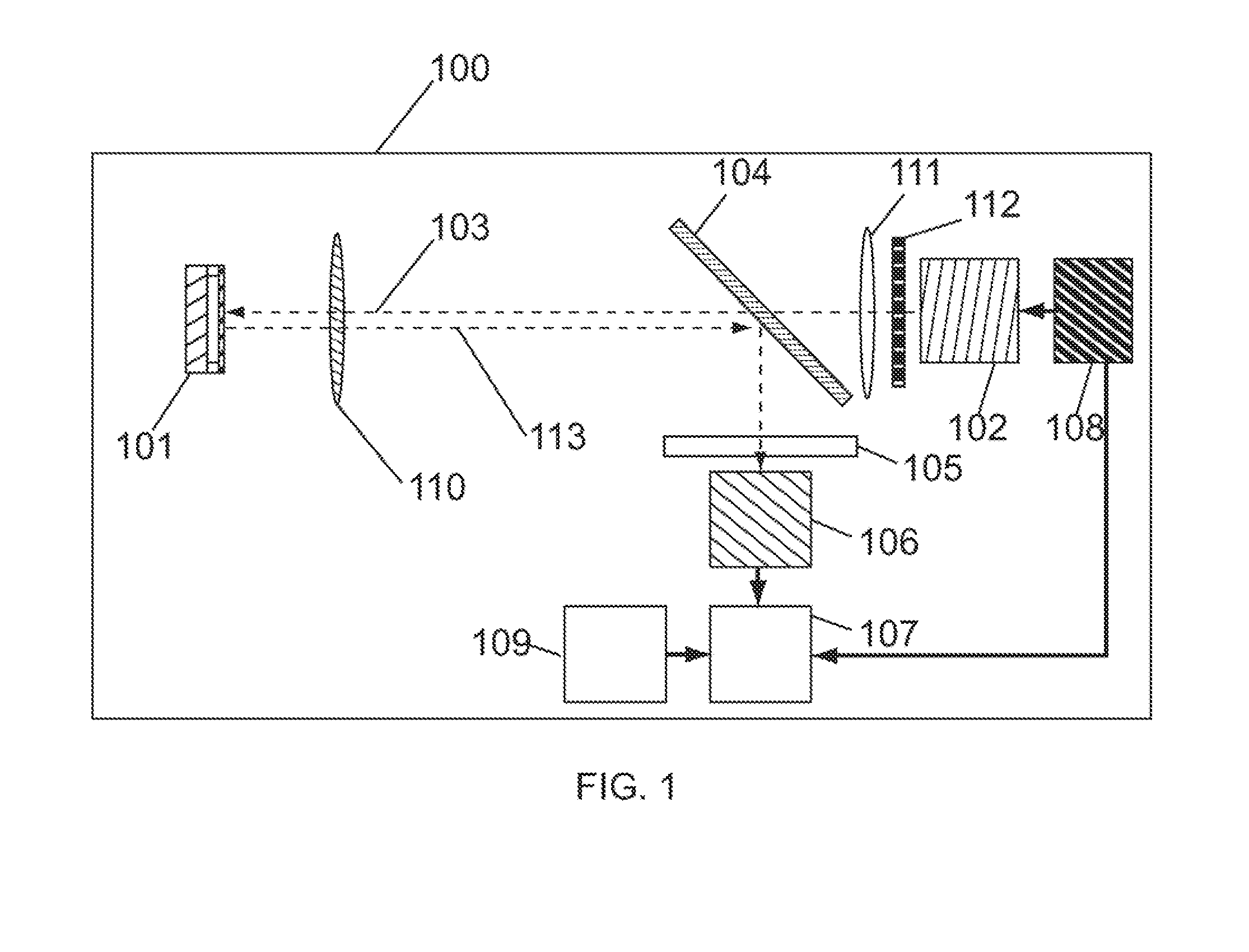
FIG. 1 shows an exemplary system 100 for frequent measurement of intraocular pressure using an intraocular (i.e., inside or within an eye) pressure sensor 101 which, in use, would be implanted in an eye. The pressure is measured optically by the system 100 using a light source 102 to illuminate the intraocular pressure sensor 101 with one or more wavelengths of incident light 103. A resultant light 113 (comprising reflected light or a combination of reflected and emitted light) is captured by a detector 106 and the signal from the detector 106 is processed by a processing device 107 to determine the intraocular pressure.

The exemplary system 100 further comprises an objective lens 110, a beam splitter 104, an illuminating lens 111, and a diffuser 112. The objective lens 110 performs at least one of the functions of collecting light from the intraocular pressure sensor 101 and forming an image of the intraocular pressure sensor 101 on the detector 106. The beam splitter 104 allows lig...


PUM


Abstract

A system for determination of intraocular pressure includes: an intraocular pressure sensor; a light source illuminating the sensor with one or more wavelengths of light; and a detector that measures emitted light from the sensor. The sensor includes a substrate member, a spacer member, and a flexible membrane, which define a sealed cavity. The flexible membrane moves in response to intraocular pressure changes. A device for measuring intraocular pressure includes: the sensor; an anchoring member attached to the sensor for immobilizing the sensor in an eye; and a protective member attached to the anchoring member and covering the sensor to prevent contact between the flexible membrane and the eye. A method for determination of intraocular pressure includes: placing the sensor in an eye; illuminating, with a light source, the sensor with one or more wavelengths of light; and detecting, with a detector, a resultant light that contains information about intraocular pressure.

Description

THE NAMES OF THE PARTIES TO A JOINT RESEARCH AGREEMENTNot applicable.INCORPORATION-BY-REFERENCE OF MATERIAL SUBMITTED ON A COMPACT DISCNot applicable.BACKGROUND OF THE INVENTION1. Field of the InventionThe present invention relates to systems, devices, and methods for measuring pressure. More particularly, the present invention relates to systems, devices, and methods for measuring intraocular pressure.2. Background ArtDevices that measure intraocular pressure (IOP) by measuring the applanation of the cornea are known in the art. Ophthalmologists use such devices to measure IOP in a physician's office. However, these single-point measurements remain insufficient to fully manage eye disease, particularly glaucoma. IOP peaks are missed in office hours measurements, IOP fluctuations may be an independent risk factor, and a majority of glaucoma patients require changes to their topical and / or surgical management approach after multiple IOP measurements on a single day. Infrequent measur...

Claims


Application Information

Patent Timeline
Patent Type & Authority Applications(United States)
IPC IPC(8): A61B3/16
CPCA61B3/165
Inventor HASTINGS, JEFFREY TODDBROCKMAN, E. BRITTST. OMER, INGRID L.WRIGHT, JOHN C.
Owner IOPTIC INC
Why Eureka
Try Eureka