Repetitive Cell Bifurcation / Side Branch Ostia Support Stent

Inactive Publication Date: 2011-06-30
BOSTON SCI SCIMED INC
View PDF4 Cites 2 Cited by
  • Summary
  • Abstract
  • Description
  • Claims
  • Application Information

AI Technical Summary

Problems solved by technology

Many prior art stents however are not wholly satisfactory for use where the site of desired application of the stent is juxtaposed or extends across a bifurcation in an artery or vein such, for example, as the bifurcation in the mammalian aortic artery into the common iliac arteries.

Method used


Image

  • Repetitive Cell Bifurcation / Side Branch Ostia Support Stent
  • Repetitive Cell Bifurcation / Side Branch Ostia Support Stent
  • Repetitive Cell Bifurcation / Side Branch Ostia Support Stent

Examples


Embodiment Construction

[0029]While this invention may be embodied in many different forms, there are described in detail herein specific embodiments of the invention. This description is an exemplification of the principles of the invention and is not intended to limit the invention to the particular embodiments illustrated.

[0030]For the purposes of this disclosure, like reference numerals in the figures shall refer to like features unless otherwise indicated.

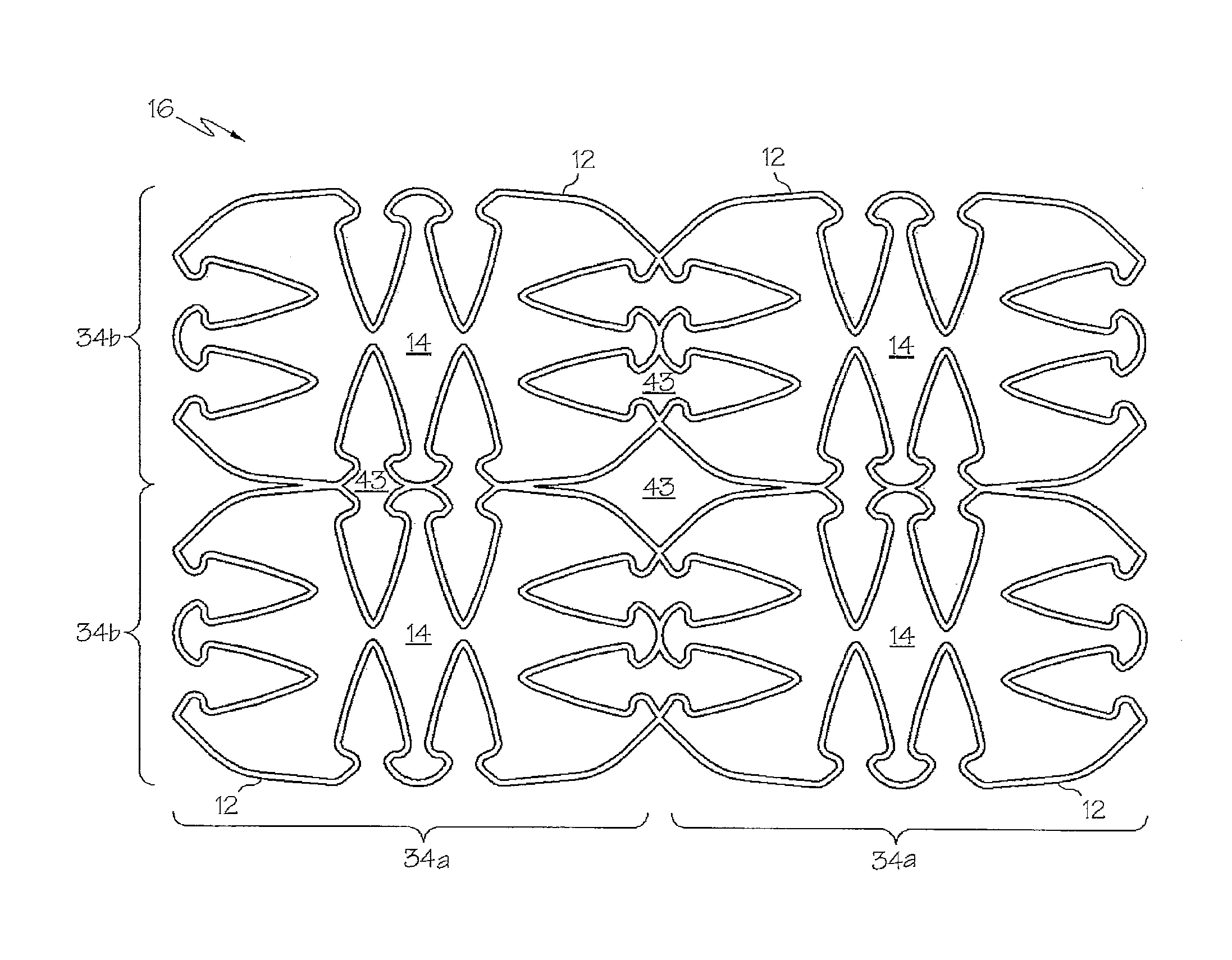
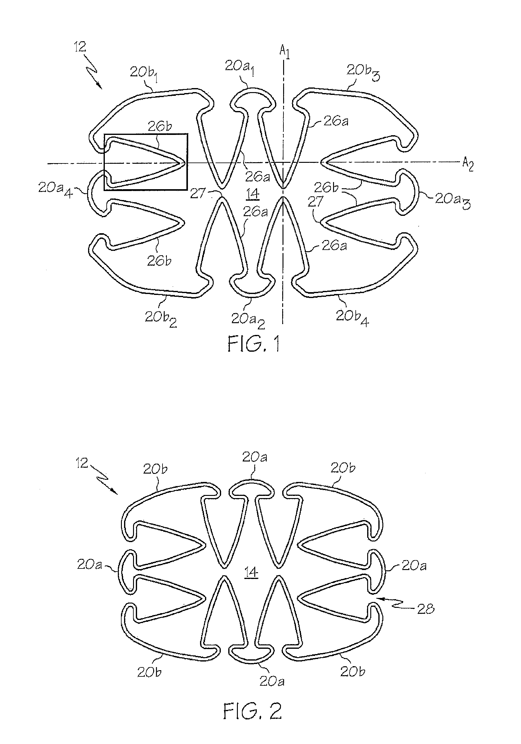
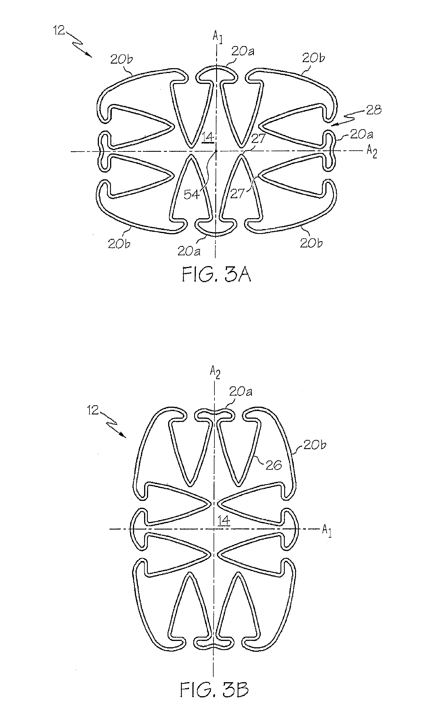
[0031]As used in this application, the stent is comprised of a plurality of members 20. Members 20 include struts 22, turns 24, petals 26, hinges 28, connectors 38, and turns 48. Each member 20 has a width, a length, and a thickness where the width is perpendicular to the length of the member 20 and the thickness of the member 20 is measured radially from the outside surface of the member 20 to the inside surface of a member 20.

[0032]Although the figures in this application show the stent 10 in a flat, plan view, in use, the stent 10 has a tubular bo...


PUM


Abstract

A stent comprises at least one closed pathway that defines a single cell. In some embodiments, the closed pathway includes a plurality of petals constructed and arranged to extend away from the tubular wall of the stent. In one embodiment, some of the petals of the closed pathway overlap other of the petals of the closed pathway when the stent is in a reduced state. In at least one embodiment, the stent comprises a plurality of closed pathways. In one embodiment, the closed pathways are arranged in bands that extend either along the length of the stent or about the circumference of the stent.

Description

CROSS-REFERENCE TO RELATED APPLICATIONS[0001]This application is a non-provisional of application No. 61 / 291,526, filed Dec. 31, 2009.STATEMENT REGARDING FEDERALLY SPONSORED RESEARCH[0002]Not ApplicableBACKGROUND OF THE INVENTION[0003]A stent is a medical device introduced to a body lumen and is well known in the art. Typically, a stent is implanted in a blood vessel at the site of a stenosis or aneurysm endoluminally, i.e. by so-called “minimally invasive techniques” in which the stent in a radially reduced configuration, optionally restrained in a radially compressed configuration by a sheath and / or catheter, is delivered by a stent delivery system or “introducer” to the site where it is required. The introducer may enter the body from an access location outside the body, such as through the patient's skin, or by a “cut down” technique in which the entry blood vessel is exposed by minor surgical means.[0004]Stents, grafts, stent-grafts, vena cava filters, expandable frameworks, an...

Claims


Application Information

Patent Timeline
IPC IPC(8): A61F2/82
CPCA61F2/856A61F2/915A61F2/91
Inventor MEYER, MICHAEL P.JULSON, ALISONMICKLEY, TIMOTHY J.
Owner BOSTON SCI SCIMED INC
Why Eureka
Try Eureka