
Method of managing parking braking in a braking system for a vehicle fitted with electric brakes

Active Publication Date: 2011-06-30
SAFRAN LANDING SYST
View PDF4 Cites 3 Cited by
  • Summary
  • Abstract
  • Description
  • Claims
  • Application Information

AI Technical Summary

Benefits of technology

[0009]An object of the invention is to provide a method of managing parking braking so as to guarantee a parking braking force while minimizing the risk of premature aging of the actuator.BRIEF DESCRIPTION OF THE INVENTION
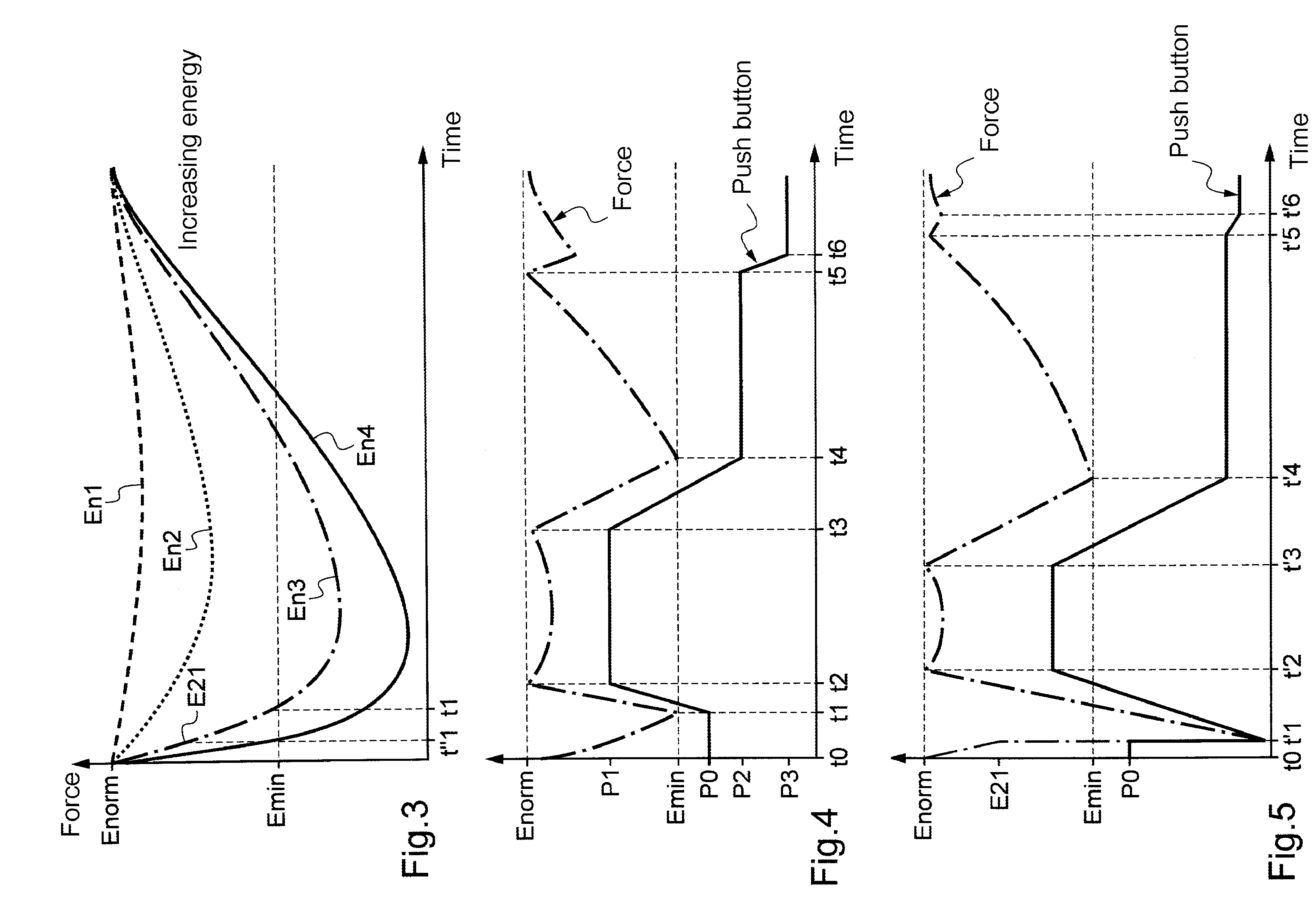
[0014]Thus, by selecting the adjustment table as a function of preceding braking, it is possible to apply the adjustment that ensures that some minimum for the parking braking force is complied with, while avoiding the risk of subjecting the brake to high levels of force as the brake cools down, thereby contributing to lengthening the lifetime of the actuators. In particular, advantage is taken of the reduction in the frequency of the adjustments and / or in the force level of each adjustment after braking operations have been performed at low intensity, thereby giving rise to small thermal expansions only.
[0015]In a first implementation of the method of the invention, a direct adjustment table is selected in association with a history of braking operations performed over a period of time preceding application of the parking brake. This therefore makes it possible to anticipate accurately the dimensional variations of the braking structure.

Problems solved by technology

Those two means consume electricity, and that can pose a problem insofar as when parked, the braking system is powered solely from the vehicle battery.
This expansion gives rise in particular to very considerable lengthening of the torsion tube that carries the disks.
Since the adjustment is the same regardless of the circumstances preceding application of the parking brake, there is a risk in certain circumstances of performing adjustments too frequently or at too high a level, such that the adjustments are of no use, particularly after braking at very low energy levels in which the thermal expansion of the torsion tube is small.
These useless adjustments contribute to prematurely aging the actuators.

Method used


Image

  • Method of managing parking braking in a braking system for a vehicle fitted with electric brakes
  • Method of managing parking braking in a braking system for a vehicle fitted with electric brakes
  • Method of managing parking braking in a braking system for a vehicle fitted with electric brakes

Examples


Embodiment Construction

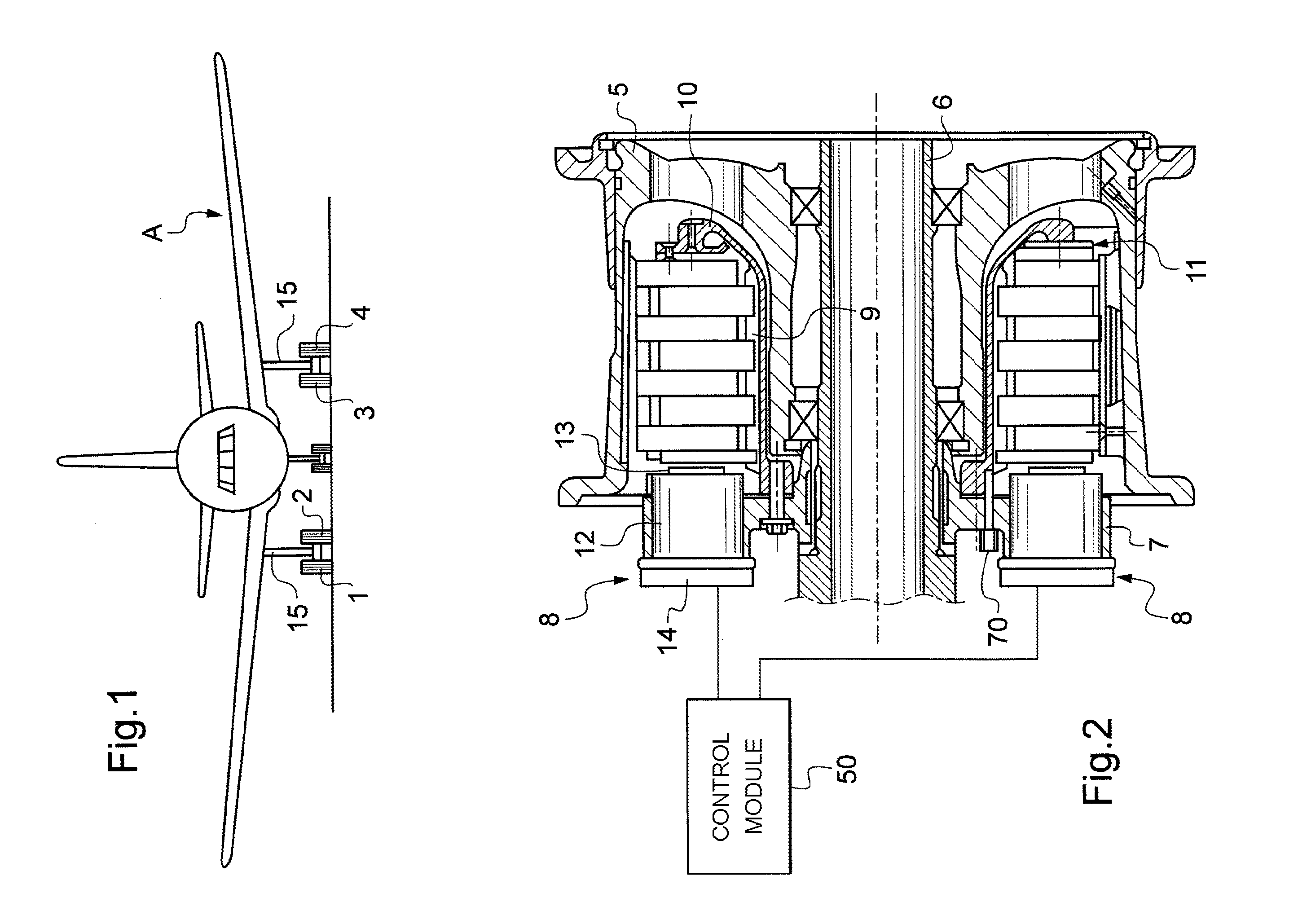
[0029]The method of the invention is described in detail herein in application to an aircraft A such as that shown in FIG. 1, which aircraft has four braked wheels numbered 1 to 4 carried by undercarriages 15. Naturally, the invention applies to an aircraft having any number of braked wheels.

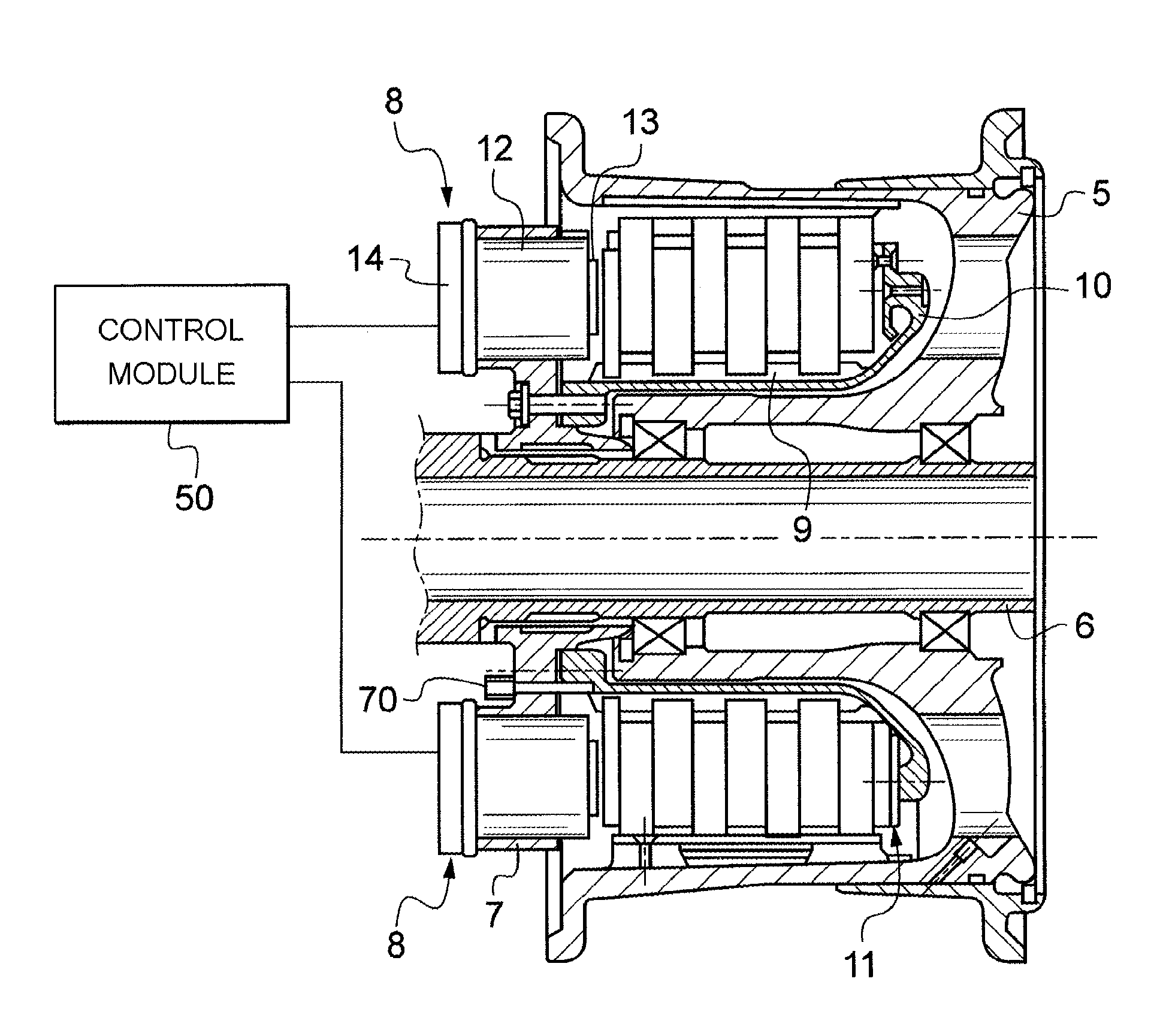
[0030]One of the braked wheels is shown in FIG. 2. Each wheel has a rim 5 adapted to receive a tire (not shown) and mounted to rotate on an axle 6 carried by one of the undercarriages 15 of the aircraft. A ring 7 carrying actuators 8 is mounted on the axle 6. The ring 7 has a torsion tube 9 fastened thereto, which tube extends inside the rim 5 and terminates in an abutment 10. The ring 7, and thus the torsion tube 9, are prevented from rotating relative to the axle 6 by stop means (not shown).

[0031]Between the abutment 10 and the actuators 8 there extends a stack of disks 11 made up of rotors that are constrained to rotate with the rim 5, and stators that are constrained to rotate with the torsi...


PUM


Abstract

The invention relates to a method of managing parking braking in a braking system for a vehicle fitted with at least one electric brake including at least one electric actuator having a pusher actuated by an electric motor for selectively applying a force against friction elements of the brake, the method comprising the steps of:establishing a series of direct adjustment tables for parking braking, corresponding to braking situations at different energy levels;when applying parking braking, selecting a direct adjustment table corresponding to a braking situation preceding the application of parking braking; anddirectly adjusting a parking braking force in application with the selected direct adjustment table.

Description

[0001]The invention relates to a method of managing parking braking in a braking system for a vehicle fitted with electric brakes.BACKGROUND OF THE INVENTION[0002]Electric brakes for a vehicle, in particular an aircraft, generally comprise at least one electric actuator having a pusher actuated by an electric motor for selectively applying a force against friction elements of the brake.[0003]In order to block the vehicle, e.g. when it is stationary on a parking space, the pusher of the actuator is put into a position in which it exerts a controlled force on the friction element, and then the pusher is blocked in this position so that it continues to exert a parking force on the friction elements, thereby allowing the power supply to the motor to be switched off and thus reducing the electrical power consumption of the brake.[0004]Nevertheless, given the dimensional variations of the components of a brake as a function of temperature, the parking force varies over time, and it is the...

Claims


Application Information

Patent Timeline
IPC IPC(8): B60T8/172
CPCB60T7/042B60T7/045B60T7/085B64C25/44B60T8/1703B60T13/74B60T13/741B60T7/107F16D49/00B60T2201/00
Inventor MUDRY, STEPHANERAGOT, FREDERICVANEY, JEAN-BAPTISTECOLIN, EMMANUEL
Owner SAFRAN LANDING SYST
Learn More