
Slipring with wear monitoring

Pending Publication Date: 2017-07-27
SCHLEIFRING GMBH
View PDF10 Cites 4 Cited by
  • Summary
  • Abstract
  • Description
  • Claims
  • Application Information

AI Technical Summary

Benefits of technology

The present invention provides a slipring with a reliable wear indicator that can alert when the slip-ring brush or the sliding track wears out. This is important because failure of the wear indication track may cause failure of the entire slipring assembly. The wear indication track-brush pair has a shorter lifetime than the remaining sliding tracks and brushes, so any failure of the wear indicator track can be easily detected. The wear indication track may have higher stress levels, allowing its components to show signs of wear earlier than other tracks and brushes. The sliding brush may wear quicker than other brushes, providing a reliable brush wear indication. There may be a sensor to detect over-temperature, electrical arcs, mechanical vibrations, or external vibration that may reduce the lifetime of the slipring assembly.

Problems solved by technology

Due to the mechanical friction there appears mechanical wear, which causes the slipring to degrade over time.
In most sliprings the sliding tracks have significantly longer lifetimes than the brushes, but these sliding tracks are also susceptible to wear.
Currently, there is no means providing an indication of the wear of sliding tracks.
For example, extremely high or low temperature may shorten a lifetime, whereas the use of the slipring at moderate temperature levels may lengthen the lifetime.
It may also detect external vibration, which further would reduce the lifetime of the slip-ring assembly.

Method used


Image

  • Slipring with wear monitoring
  • Slipring with wear monitoring
  • Slipring with wear monitoring

Examples


Embodiment Construction

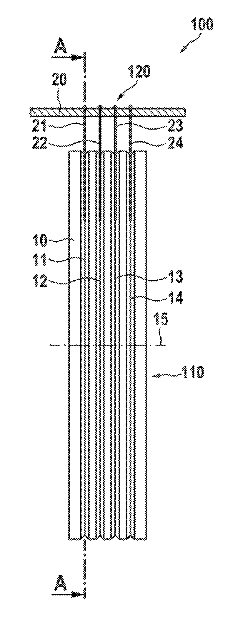
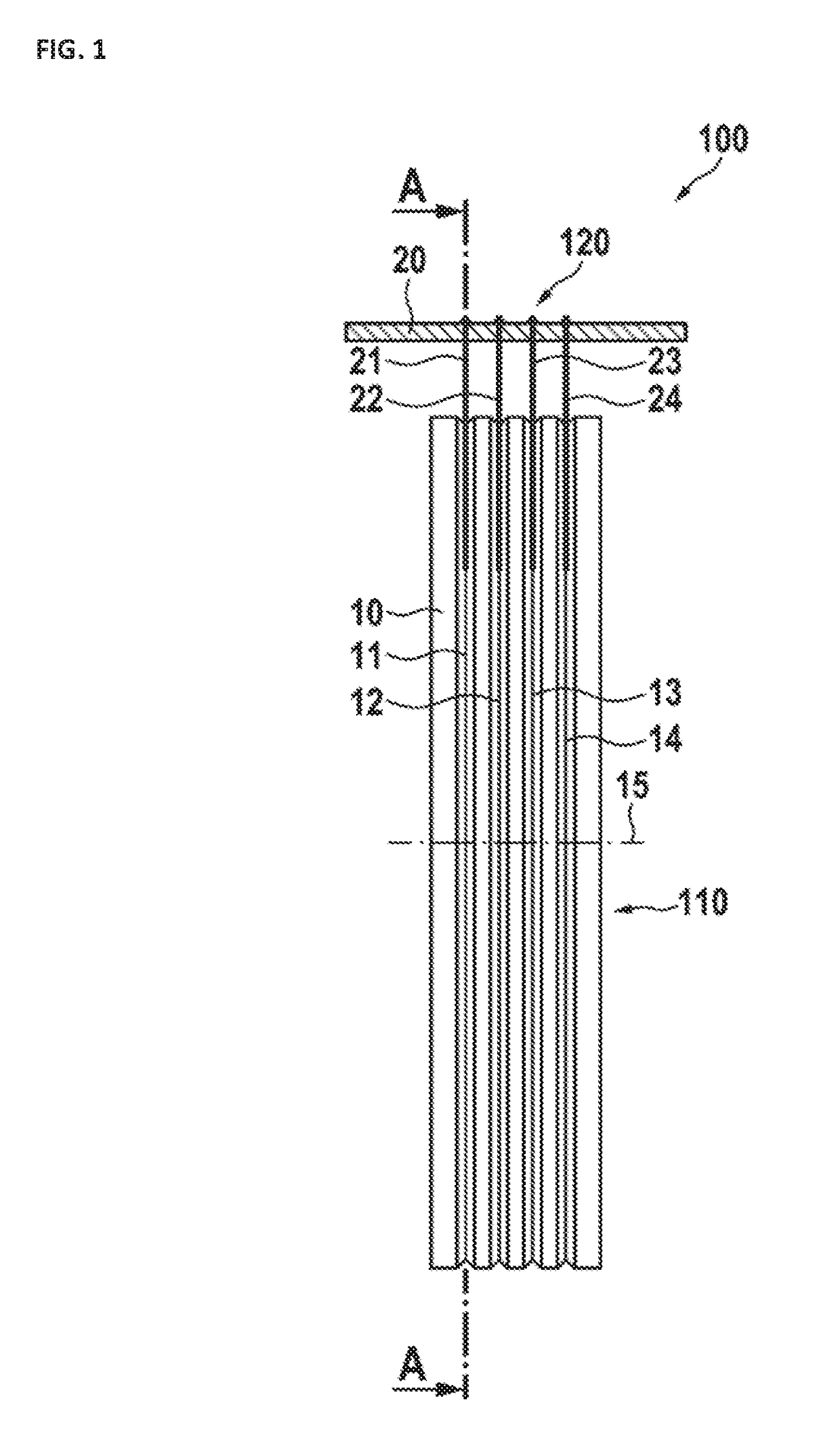
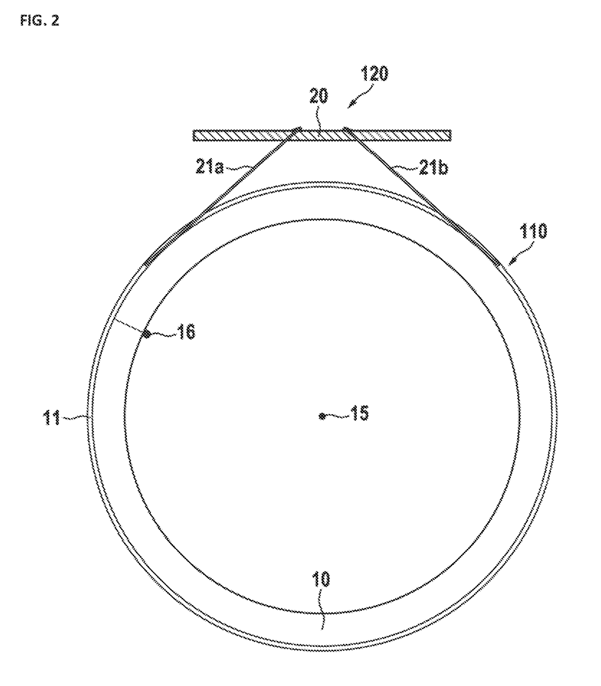
[0030]In FIG. 1, a side view of a preferred embodiment is shown. A slipring assembly 100 comprises a slipring module 110 and a slipring brush block 120. The slipring module 110 may rotate about the rotation axis 15 and comprises an isolating body 10 having a plurality of sliding tracks. Here, four sliding tracks 11, 12, 13, and 14 are shown, although there may be any other number of sliding tracks present. The sliding tracks are embedded in and / or held by the isolating body 10. Preferably, the sliding tracks are isolated from each other. There may also be configurations, where at least some of the sliding tracks are connected together electrically. Such configurations may be useful for transferring higher currents or signals with lower levels of noise. Here, a preferred embodiment of sliding tracks having V-shaped grooves is shown. These V-grooves provide the advantage that they can guide wires sliding on them and keep the wires precisely on predetermined tracks. Any other type of s...


PUM


Abstract

A slipring with at least one slip ring module having at least one sliding track, and at least one wear indication track. A wear indication circuit is connected to the at least one wear indication track for monitoring electrical properties of the wear indication track and signaling an abnormal slipring condition. A wear indication track may be exposed to higher load, higher rotation speed, higher brush pressure force, or other lifetime-reducing influence as compared to a normal sliding track.

Description

CROSS-REFERENCE TO RELATED APPLICATIONS[0001]This application is a continuation of pending International Application No. PCT / EP2015 / 073764 filed on Oct. 14, 2015, which designates the United States and claims priority from the European Application No. 14188832.1, filed on Oct. 14, 2014. The disclosure of each of the above-identified patent documents is incorporated herein by reference.BACKGROUND[0002]1. Field of the Invention[0003]The invention relates to slip-rings for transmission of electrical signals between rotating parts. Specifically, it relates to wear monitoring in context of transmission of electrical signals between the rotating parts and a slip-ring device with improved wear monitoring.[0004]2. Description of Relevant Art[0005]Electrical slipring devices are used to transfer electrical power and / or signals between a rotating part and a stationary part of a given system. Such devices are used in different applications, such as wind energy plants or computer tomography sca...

Claims


Application Information

Patent Timeline
IPC IPC(8): H01R39/58H01R39/56H01R39/08H01R39/22H01R43/12
CPCH01R39/58H01R39/22H01R39/56H01R39/08H01R43/12
Inventor HOLZAPFEL, CHRISTIANHERMANN, MATTHIASSTEFFENS, HOLGERHAFFNER, HOLGER
Owner SCHLEIFRING GMBH
Learn More