
System and method for condition-based filter changes

Pending Publication Date: 2022-03-10
POSEIDON SYST LLC
View PDF0 Cites 0 Cited by
  • Summary
  • Abstract
  • Description
  • Claims
  • Application Information

AI Technical Summary

Benefits of technology

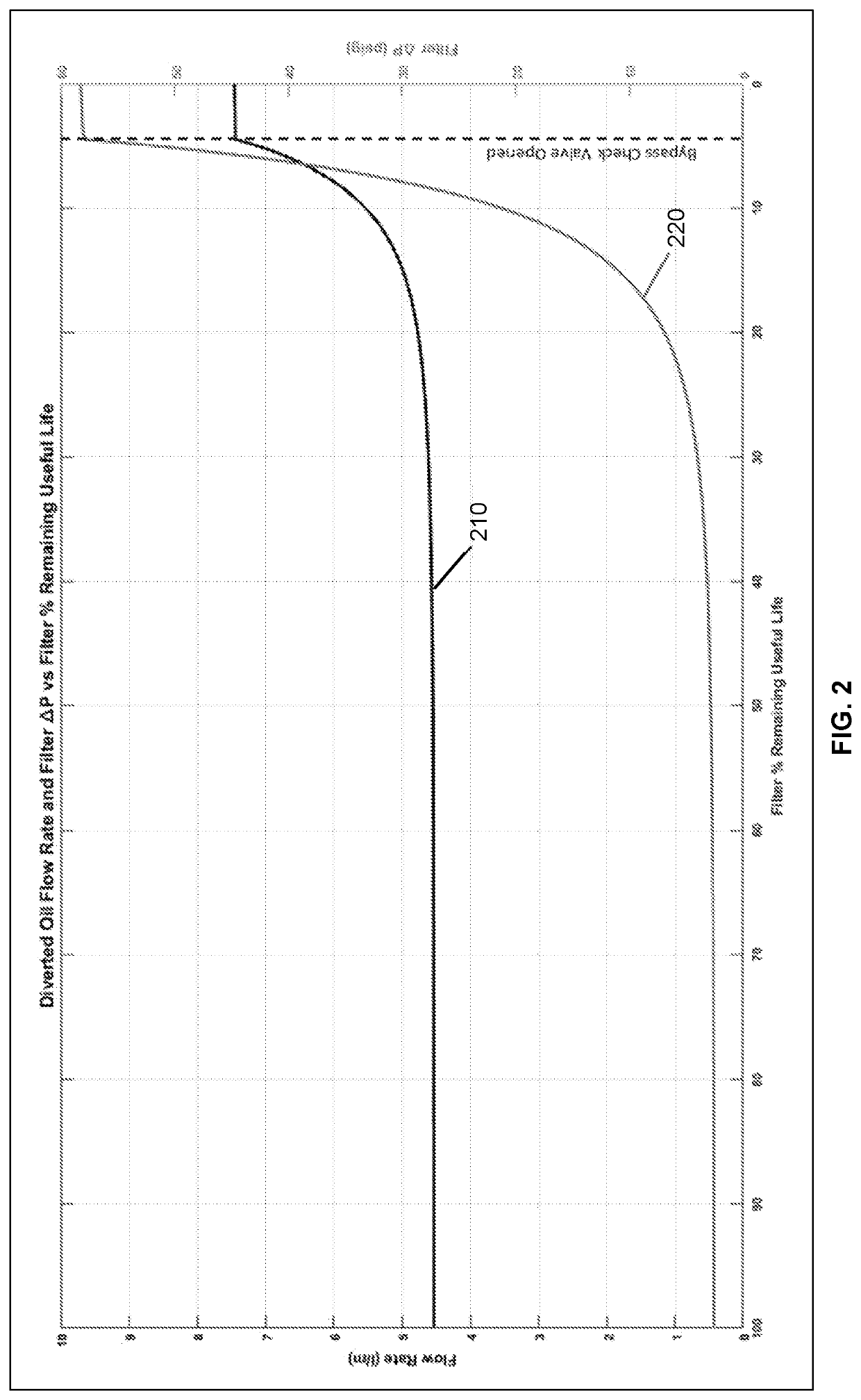
The patent describes a system and method for estimating the remaining useful life of a lubrication filter used in various machines and equipment. The system measures the flow rate of oil that is diverted from the main filtration system and uses this information to calculate the percentage of useful life remaining. This approach is different from previous methods that required multiple sensors and oil ports to make the determination. The system uses a single flow rate measurement and takes into account factors such as oil quality, system runtime, and oil temperature to estimate the remaining useful life of the filter. This allows for better maintenance and replacement of the filter at the right time, reducing downtime and wear and tear on the machinery.

Problems solved by technology

As a result, time-based filter changes often cause either a filter to be changed before it is actually necessary or a filter change after the filter has reached its load capacity and is no longer providing adequate filtration to the lubrication fluid.

Method used


Image

  • System and method for condition-based filter changes
  • System and method for condition-based filter changes

Examples


Embodiment Construction

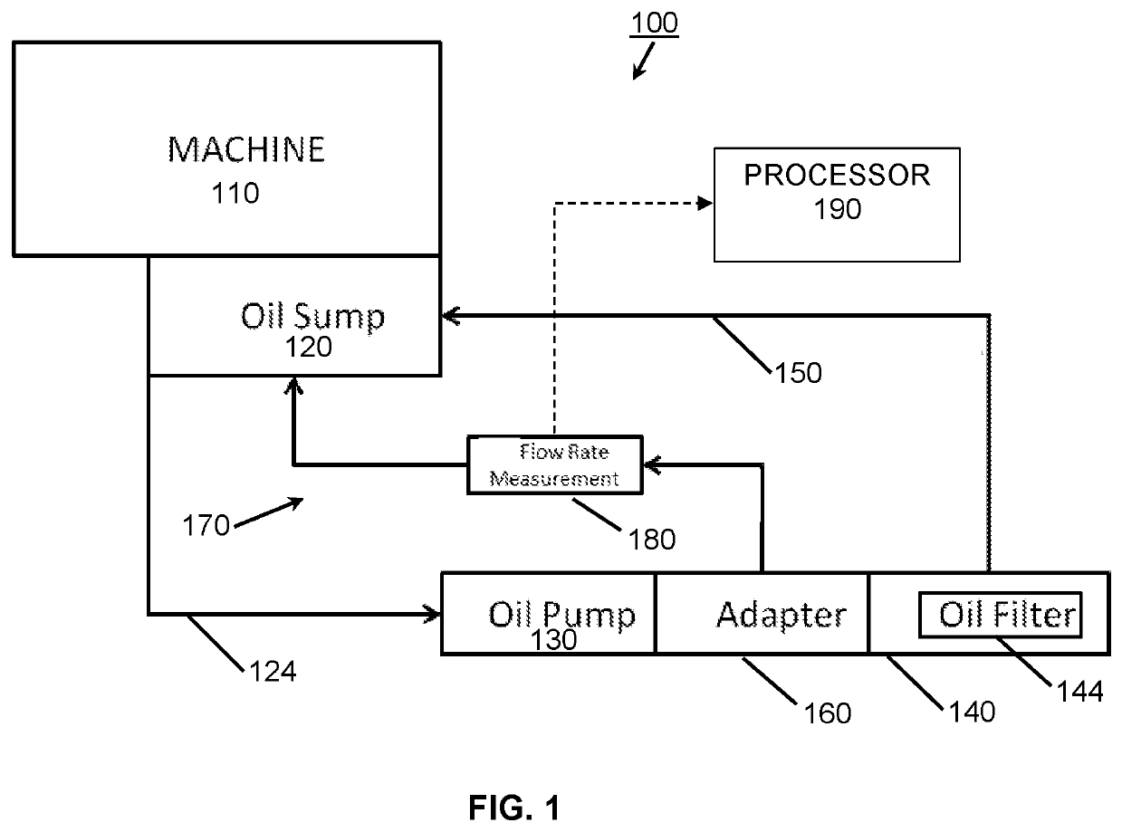
[0012]FIG. 1 is an illustration of an exemplary lubrication fluid (e.g. oil) filtration system 100 suitable for carrying out the methods disclosed herein. A filtration system 100 is generally associated with a machine or piece of equipment 110, and includes or consists of an oil sump 120, and the sump is sometimes the machine or equipment housing itself. Also included is a hydraulic inlet line 124 that feeds fluid from the sump 120 to a pump 130. In one embodiment the pump may be a positive displacement gear oil pump or any similarly configurable pumping mechanism. In a typical configuration, a filter housing 140 has a replaceable filter element 144 located therein, and the housing assures that the lubrication fluid pumped into the housing passes through the filter element to a hydraulic return line 150 that returns filtered oil to the machine 110, such as to the associated sump 120.

[0013]Also depicted as part of the filtration system of FIG. 1 is a filter bypass adapter or componen...


PUM

PropertyMeasurementUnit
Temperatureaaaaaaaaaa
Pressureaaaaaaaaaa
Flow rateaaaaaaaaaa

Abstract

A method and system for estimating the remaining useful life of a filter in a lubrication system is disclosed along with exemplary system components.

Description

[0001]Described herein is a system and method for determining the remaining useful life of an oil or lubrication filter element, for example an oil filter element used with gearboxes, turbines, internal combustion engines, and other machinery that utilize positive displacement lube oil filtration systems.BACKGROUND AND SUMMARY[0002]Mechanical systems and equipment frequently employ gearboxes, internal combustion engines, and turbines that require lubrication systems to lubricate moving components with oil, or similar lubricating fluids. Non-limiting examples of components that require such lubrication include, gears / gearing and bearings and similar mechanical components that are in contact with one another. The use of lubricating fluids protects such components from wear and corrosion, provides means of cooling, and flushes and removes contaminants from the components and the wear surfaces.[0003]The embodiments disclosed herein are directed to a method for determining or estimating ...

Claims


Application Information

Patent Timeline
IPC IPC(8): B01D35/143B01D37/04B01D35/26B01D35/00B01D35/147F16H57/04F01M11/10F16N39/06
CPCB01D35/143B01D37/043B01D35/26B01D35/005B01D35/147F01M11/0004F16H57/0404F01M11/10F16N39/06B01D2201/54F16H57/0436F16H57/0405B01D29/60B01D37/04B01D35/027F01M2011/0029F01M2011/14F16N13/20F16N2230/02F16N2250/40F16N2260/18F01M1/10
Inventor PELKEY, ALEXANDER T.MARVIN, TIMOTHY R.BREWER, RYAN C.
Owner POSEIDON SYST LLC
Learn More